

MMO/Ti flexible anodes are used in impressed current cathodic protection systems for buried pipelines, station areas, airport apron pipe networks, and storage tank bottoms. This guide explains how to evaluate flexible anode quality, including coating type, internal cable, connection nodes, design life, inspection, packaging, and installation requirements, helping buyers choose a suitable product before inquiry.

Introduction
In cathodic protection systems for buried pipelines, station areas, airport apron pipe networks, and storage tank bottoms, the choice of anode material directly affects whether the protection current can remain stable, whether the system service life is reliable, and whether future maintenance will be manageable.
For many buyers who are not familiar with cathodic protection products, a flexible anode may look like a long cable-shaped product. However, an MMO/Ti flexible anode is not a simple cable. It is an integrated auxiliary anode system composed of MMO/Ti anode wire, internal cable, coke breeze filler, wrapping fabric, wear-resistant braided mesh, and conductive connection nodes.
If buyers only compare prices or appearance, it is difficult to judge whether a flexible anode is truly suitable for a project. A reliable flexible anode should meet requirements for electrochemical performance, structural integrity, node reliability, installation adaptability, and long-term service stability.
This article explains the basic concept, application scope, product structure, common product models, selection logic under different application environments, key performance indicators, inspection and acceptance points, packaging and storage requirements, installation requirements, and common buyer questions. The goal is to help purchasing teams, project engineers, and cathodic protection users better understand how to evaluate MMO/Ti flexible anodes before procurement.

1. Understanding MMO/Ti Flexible Anodes: Basic Concept, Application Scope, and Product Structure
For buyers who are new to cathodic protection products, a flexible anode may look like a long anode cable. In actual engineering applications, however, it is not an ordinary cable or a simple metal anode. It is a composite auxiliary anode product that integrates anode material, conductive cable, coke breeze filler, outer wrapping layer, wear-resistant protection layer, and conductive connection nodes.
In cathodic protection systems for buried pipelines, station areas, airport apron pipe networks, and storage tank bottoms, a flexible anode supplies protective current to the protected metal structure through an impressed current system. Its main advantage is that it can be installed continuously along the protected structure, helping to distribute current more evenly. This makes it especially suitable for complex underground environments, dense pipeline areas, changing soil conditions, or projects where later maintenance is difficult.
1.1 What Is an MMO/Ti Flexible Anode?
An MMO/Ti flexible anode is a long-line auxiliary anode used in impressed current cathodic protection systems.
MMO stands for Mixed Metal Oxide. Ti refers to titanium. In other words, the core anode material of an MMO/Ti flexible anode is usually titanium wire coated with mixed metal oxide.
From a functional point of view, the MMO/Ti wire is responsible for the anode reaction and current output. The internal cable is responsible for current transmission. The coke breeze filler improves the conductive environment around the anode. The outer wrapping layer and wear-resistant braided mesh protect the internal structure. The connection nodes provide reliable electrical connection between the MMO/Ti wire and the internal cable.
Therefore, when evaluating the quality of a flexible anode, buyers should not only check whether the appearance is complete or ask the price per meter. More important factors include the anode core material, coating type, cable cross-sectional area, node quality, filler condition, outer protection structure, and whether the product is suitable for the actual project environment.
1.2 Where Are Flexible Anodes Commonly Used?

MMO/Ti flexible anodes are mainly used in cathodic protection systems in soil environments. Common application scenarios include buried pipelines, station areas, airport apron pipe networks, and storage tank bottom protection.
For buried pipeline cathodic protection, flexible anodes can be installed parallel to the pipeline. This allows the protection current to be distributed more continuously along the pipeline length. In areas where the pipeline route is complex, local soil conditions vary significantly, or conventional anode beds cannot provide uniform coverage, flexible anodes can help improve the stability of the protection effect.
In station areas, underground facilities are often dense. There may be multiple pipelines, cables, grounding electrodes, and other metallic structures in the same area. Current distribution in such environments is more complicated. Flexible anodes can be arranged in sections or around specific structures according to the station layout, which helps improve current coverage and protection uniformity.
For airport apron pipe networks and other concealed engineering projects, future excavation and maintenance can be expensive and difficult. If the project requires better fault location capability, a break-detectable flexible anode can be considered. This type of anode helps locate a break point if the anode is damaged during service.
For storage tank bottom cathodic protection, flexible anodes are usually installed under the tank bottom in the designed area. They may be arranged in concentric rings or in a serpentine layout so that the protection current can cover the external surface of the tank bottom. For this type of project, the anode length, spacing, rated output current, and design life should be calculated according to the tank size, protection current density, and expected service life.
In general, flexible anodes are suitable for cathodic protection projects that require continuous protection, more uniform current distribution, flexible installation layout, and better long-term maintenance planning.
1.3 What Is the Structure of a Flexible Anode? How Should Common Models Be Understood?

A complete MMO/Ti flexible anode usually consists of MMO/Ti wire, internal cable, coke breeze filler, wrapping fabric, wear-resistant braided mesh, and connection nodes.
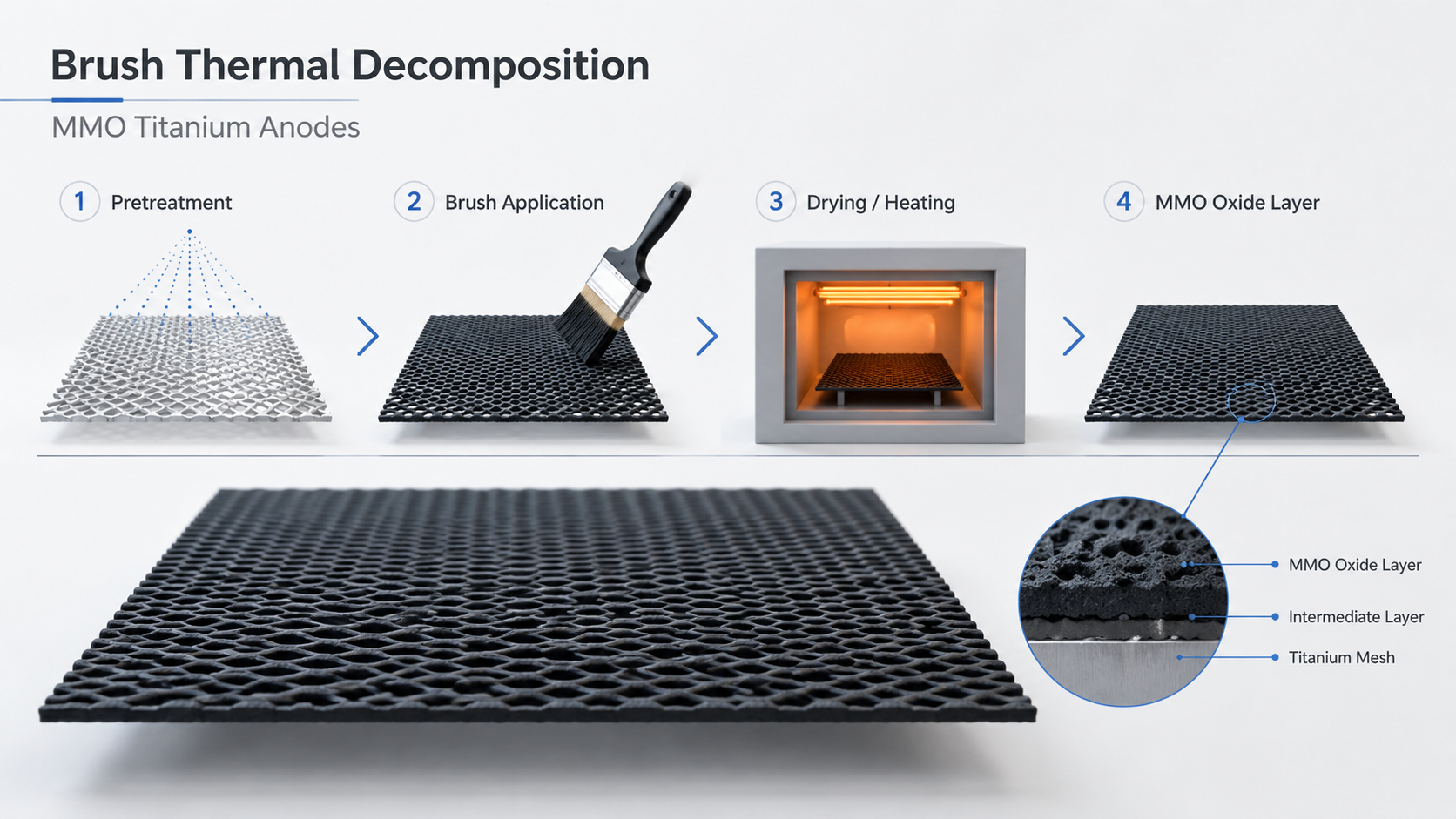
The MMO/Ti wire is the core part of the flexible anode. It uses titanium wire as the substrate, with a mixed metal oxide coating on the surface. It is responsible for the anode reaction and current output. When evaluating this part, buyers should pay attention to the MMO/Ti wire diameter, coating type, coating thickness, and coating adhesion.
The internal cable is usually a continuous single-core stranded copper cable. It is mainly used for current transmission. The copper core cross-sectional area should meet the output current requirement of the flexible anode. At the same time, the cable sheath should be suitable for soil conditions, temperature, groundwater level, and possible biological damage.
The coke breeze filler surrounds the anode core material and helps improve the conductive environment near the anode, making current output more stable. The wrapping fabric holds the coke breeze filler in place and prevents filler leakage. The wear-resistant braided mesh is located on the outer layer and improves resistance to friction, scraping, and mechanical damage during transportation, installation, and backfilling.
The connection nodes are the conductive connection points between the MMO/Ti wire and the internal cable. Node quality directly affects current transmission stability and long-term operating reliability. A qualified flexible anode should not only have reliable anode wire performance, but also firm node connection, low contact resistance, and good sealing performance.
In terms of model expression, common flexible anodes include FA series and FApro series. FA usually refers to ordinary flexible anodes. FApro usually refers to break-detectable flexible anodes. Break-detectable flexible anodes are suitable for concealed projects or projects with difficult future maintenance because they help locate the break point if the anode is damaged.
For example, in the model FA-1016α:
FA means flexible anode.
10 means the nominal diameter of the MMO/Ti wire is 1.0 mm.
16 means the effective cross-sectional area of the internal cable copper core is 16 mm².
α means the MMO/Ti wire coating is an iridium oxide-tantalum oxide coating.
For another example, in the model FApro-1016β:
FApro means break-detectable flexible anode.
10 means the nominal diameter of the MMO/Ti wire is 1.0 mm.
16 means the effective cross-sectional area of the internal cable copper core is 16 mm².
β means the MMO/Ti wire coating is a ruthenium oxide-iridium oxide coating.
Common MMO/Ti wire diameters include 0.8 mm, 1.0 mm, 1.5 mm, and 2.0 mm. Common internal cable copper core cross-sectional areas include 10 mm², 16 mm², and 25 mm². Different combinations of anode wire diameter, cable cross-sectional area, and coating type form different flexible anode models.
Common Product Models
| Model | MMO/Ti Wire Diameter (mm) | Cable Copper Core Cross-Sectional Area (mm²) |
|---|---|---|
| FA-0810α, FA-0810β, FApro-0810α, FApro-0810β | 0.8 | 10 |
| FA-0816α, FA-0816β, FApro-0816α, FApro-0816β | 0.8 | 16 |
| FA-0825α, FA-0825β, FApro-0825α, FApro-0825β | 0.8 | 25 |
| FA-1010α, FA-1010β, FApro-1010α, FApro-1010β | 1.0 | 10 |
| FA-1016α, FA-1016β, FApro-1016α, FApro-1016β | 1.0 | 16 |
| FA-1025α, FA-1025β, FApro-1025α, FApro-1025β | 1.0 | 25 |
| FA-1510α, FA-1510β, FApro-1510α, FApro-1510β | 1.5 | 10 |
| FA-1516α, FA-1516β, FApro-1516α, FApro-1516β | 1.5 | 16 |
| FA-1525α, FA-1525β, FApro-1525α, FApro-1525β | 1.5 | 25 |
| FA-2010α, FA-2010β, FApro-2010α, FApro-2010β | 2.0 | 10 |
| FA-2016α, FA-2016β, FApro-2016α, FApro-2016β | 2.0 | 16 |
| FA-2025α, FA-2025β, FApro-2025α, FApro-2025β | 2.0 | 25 |
Ehisen can provide common MMO/Ti flexible anode models and can also offer processing and customization services according to the customer’s soil environment, design life, output current, installation space, and whether break-detection function is required. If buyers are not sure which model to choose, it is recommended to provide the application scenario, soil conditions, design life, current demand, and installation requirements during inquiry so that a more suitable product solution can be reviewed.

2. How to Select and Specify Flexible Anodes Under Different Application Conditions
The selection of a flexible anode should not be based only on the model number. The real application suitability depends on soil conditions, salinity, groundwater level, environmental temperature, possible termite damage, required design life, output current, installation method, and maintenance requirements.
The following points are especially important for buyers.
2.1 General Appearance and Dimensional Requirements
A qualified flexible anode should have a uniform and complete surface. There should be no filler leakage, and the wear-resistant braided mesh should have no broken wires or skipped wires. Although appearance inspection seems basic, it reflects the overall production control of the product.
The outer diameter of the product cross-section is usually controlled at 38 ± 2 mm. The linear density should be greater than 1.30 kg/m. If the linear density is too low, it may indicate insufficient filler, loose structure, or non-compliant product composition. For buyers, outer diameter and linear density are two direct and practical acceptance indicators.
When purchasing flexible anodes, buyers are advised to request the following information:
Product model and structure description.
Outer diameter control range.
Linear density requirement.
Appearance acceptance standard.
Packaging unit and length per reel.
Product certificate and quality documents.
2.2 MMO/Ti Wire Requirements: The Coating Type Should Match the Soil Environment
The MMO/Ti wire should use titanium wire as the substrate, and the chemical composition and performance of the titanium wire should meet the relevant requirements. For buyers, the more important points are coating type, coating adhesion, and coating thickness.
2.2.1 Coating Adhesion
The MMO/Ti wire coating should be firmly bonded to the titanium substrate and should not peel off. A common test method is to take a certain length of MMO/Ti wire, bend it 180° around a metal rod with a diameter of 20 mm, and observe whether the coating peels off.
This test helps evaluate whether the coating can remain reliable under bending and installation conditions.
For flexible anodes, bending performance is very important. If the coating peels off during bending, even if the initial electrochemical performance looks acceptable, there may still be a risk of local failure during long-term operation.
2.2.2 Coating Thickness
The coating thickness of MMO/Ti wire should generally be greater than or equal to 6 g/m². Coating thickness should not be judged only by surface color. It is closely related to anode life, current output, and application environment.
In a project, buyers should clearly specify the coating type and coating thickness requirement. If necessary, related inspection or quality documents should be requested from the supplier.
2.2.3 Coating Selection for Non-Saline Soil and Saline Soil
In non-saline soil environments, flexible anodes should use MMO/Ti wire with an iridium oxide-tantalum oxide coating.
In saline soil or saline-alkali soil environments, flexible anodes should use MMO/Ti wire with a ruthenium oxide-iridium oxide coating.
This is an important selection point that many buyers may overlook. Both products are MMO/Ti flexible anodes, but different soil environments lead to different electrode reaction conditions. Therefore, the coating system should also be selected accordingly.
When purchasing, buyers should not only say, “We need an MMO flexible anode.” It is better to provide information such as whether the soil is saline, whether the site is saline-alkali land, groundwater conditions, and expected service life.
2.3 Internal Cable Requirements: Conductivity and Sheath Suitability Are Both Important
The internal cable of a flexible anode should be a continuous single-core stranded copper cable. The copper core cross-sectional area should meet the output current requirement of the flexible anode and should not be less than 10 mm². In common product models, the cable copper core cross-sectional area may be 10 mm², 16 mm², or 25 mm².
2.3.1 Why Is Copper Core Size Not the Only Factor?
The copper core cross-sectional area affects current transmission capacity, but it is not the only factor. In long-term underground service, the cable sheath must also maintain reliable insulation.
If the sheath material cannot withstand soil corrosion, temperature changes, or groundwater conditions, the insulation life of the cable may be shorter than the expected life of the project.
2.3.2 How to Select the Cable Sheath According to the Environment
The selection of the internal cable sheath should consider the following factors:
The corrosive effect of the soil environment on the sheath.
The influence of electrode reaction products on the MMO/Ti wire surface.
The environmental temperature during flexible anode installation.
Possible biological damage.
The effect of cable heat diffusion on sheath performance when soil thermal resistance is high.
Environmental protection requirements of the project.
In non-saline soil environments, the internal cable may use a high-density or high-molecular-weight polyethylene outer sheath.
In saline soil or saline-alkali soil environments, the internal cable may use a fluoropolymer-insulated high-density polyethylene outer sheath or a cross-linked polyethylene outer sheath.
If the groundwater level is higher than the burial depth of the flexible anode, the internal cable should use a sheath with low water permeability. A polyethylene outer sheath is preferred.
If the operating environment temperature is below -15°C, the internal cable should use a cross-linked polyethylene, polyethylene, or cold-resistant rubber insulation sheath. Polyvinyl chloride insulation sheath is not recommended.
If the operating environment temperature is above 60°C, the internal cable should use a heat-resistant sheath, such as heat-resistant PVC, cross-linked polyethylene, or ethylene-propylene rubber insulation. Ordinary PVC insulation sheath is not recommended.
In areas with serious termite damage, the internal cable should use a sheath with higher hardness. In areas with a higher termite hazard level, anti-termite performance should also be considered.
These requirements show that a flexible anode is not just an anode cable. It is an engineering product that should be selected according to the service environment. When communicating with customers about flexible anode projects, Ehisen recommends that customers provide soil conditions, temperature range, groundwater situation, termite risk, design life, and output current demand so that the product structure can be matched more accurately.
2.4 Connection Node Requirements: Node Quality Directly Affects Long-Term Reliability
The connection node is the conductive connection point between the MMO/Ti wire and the copper core of the internal cable. The node should be firm. The node spacing should be less than or equal to 5 m, and the node position deviation should not be greater than 10% of the spacing.
The node contact resistance should be less than or equal to 0.0009 Ω. This is a very important indicator. Lower contact resistance means more stable electrical connection. If node contact resistance is too high, it may cause uneven current transmission, local heating, or unstable operation.
The insulation sealing structure at the node should also have sufficient waterproof performance. The sealing structure should pass the required waterproof test, and water should not enter the node after testing.
For buried cathodic protection systems, nodes are often exposed to wet soil or groundwater for a long time. Node sealing failure may be more hidden than anode material failure and is more difficult to repair after installation.
Therefore, when purchasing flexible anodes, buyers should ask the following questions:
What is the node spacing?
Is the node position controlled?
Is node contact resistance tested?
Has the node sealing structure passed waterproof verification?
If the product is supplied in sections or connected on site, how is joint resistance controlled?
Can the supplier provide related inspection records or quality documents?
2.5 Requirements for Coke Breeze Filler, Wrapping Fabric, and Wear-Resistant Braided Mesh
The coke breeze filler should use calcined petroleum coke. The fixed carbon content should not be less than 90%, and the volume resistivity should not be greater than 0.06 Ω·cm. The particle size should also meet the relevant requirements to ensure conductivity and structural stability.
The wrapping fabric should have sufficient bursting strength, wear resistance, and puncture strength. The coverage density of the wear-resistant braided mesh should be greater than or equal to 60%, and the monofilament diameter should generally be greater than or equal to 0.8 mm.
These structural materials protect the internal MMO/Ti wire, cable, and coke breeze filler. They reduce the risk of structural damage during transportation, unreeling, installation, backfilling, and long-term buried service.
During acceptance inspection, buyers should not only focus on electrical performance. They should also check whether the outer layer is complete, whether the braided mesh is uniform, and whether there is obvious damage, filler leakage, or local looseness.

3. How to Determine Key Performance Indicators of Flexible Anodes
The key performance indicators of flexible anodes mainly include minimum bending radius, design life, and operating performance. Understanding the principles behind these indicators helps buyers judge whether the product parameters provided by the supplier are reasonable.
3.1 Minimum Bending Radius: Why Flexible Does Not Mean It Can Be Bent Freely
Although it is called a flexible anode, it does not mean that it can be bent without limitation. A flexible anode contains MMO/Ti wire and internal cable. If the bending radius is too small, the titanium wire, coating, cable, or outer wrapping structure may be damaged.
The minimum bending radius of the product should satisfy the following relationship:
R ≤ 1.6 × max(Rcable,Rmmo)
In this formula:
R is the minimum bending radius of the product.
Rcable is the minimum bending radius of the internal cable.
Rmmo is the minimum bending radius of the internal MMO/Ti wire.
The minimum bending radius of the MMO/Ti wire can be understood by the following formula:
Rmmo = K × d
In this formula:
K is the bending coefficient of the MMO/Ti wire.
d is the diameter of the MMO/Ti wire.
The K value is usually related to the application environment, chemical composition of the titanium wire substrate, mechanical properties, heat treatment condition, MMO coating type, and coating thickness. The common value range is 3 to 25.
This means that the bending ability of a flexible anode is not fixed. It is affected by the cable, titanium wire, coating, and overall product structure.
In general, a larger MMO/Ti wire diameter may provide higher current carrying capacity and longer service life under certain conditions, but the bending requirement during installation should also be handled more carefully.
Therefore, in trench corners, storage tank bottom ring layouts, serpentine layouts, and other bending areas, buyers and installation teams should confirm the allowable bending radius in advance. Forced bending on site should be avoided because it may cause hidden damage.
3.2 Design Life: It Should Be Linked to Output Current, Not Only to a Number of Years
Design life refers to the expected service time during which the flexible anode does not lose its function under the cathodic protection system design conditions.
For flexible anodes, design life is closely related to MMO/Ti wire diameter, coating type, rated output current, and service environment.
For example, for an MMO/Ti flexible anode with iridium oxide-tantalum oxide coating, the relationship between rated output current and design life can be understood as follows:
| MMO/Ti Wire Diameter | Rated Output Current for 25 Years | Rated Output Current for 30 Years | Rated Output Current for 40 Years | Rated Output Current for 50 Years |
|---|---|---|---|---|
| 1.0 mm | 52 mA/m | 43 mA/m | 33 mA/m | 26 mA/m |
| 1.5 mm | 78 mA/m | 65 mA/m | 49 mA/m | 39 mA/m |
| 2.0 mm | 104 mA/m | 87 mA/m | 65 mA/m | 52 mA/m |
This table shows that for the same MMO/Ti wire diameter, a longer design life usually corresponds to a lower allowable rated output current. Under the same design life, a larger MMO/Ti wire diameter can provide a higher rated output current.
This is very important for buyers. When purchasing flexible anodes, it is not enough to ask, “How many years can it be used?” Buyers should also confirm, “At what output current can it reach this design life?”
If a supplier only provides a service life number without explaining the corresponding output current condition, the life statement is incomplete.
3.3 Operating Performance: Why Is a 3% NaCl Solution Test Used?
The operating performance of a flexible anode can be verified by continuous operation testing under simulated conditions.
A common method is to place the product in a 3% NaCl solution and apply a specified current of 100 A/m². The specified current can be calculated using the following formula:
itest = 100 × π × d × L
In this formula:
itest is the specified current applied to the sample, in mA.
d is the diameter of the MMO/Ti wire inside the flexible anode, in mm.
L is the length of the flexible anode test sample, in m.
After the product works continuously under the specified current for 15 days, it should meet the following requirements:
The product can still operate under the initial current output, and the voltage deviation of the regulated power supply remains within ±10% during the test.
The MMO/Ti wire and the cable copper core at the node remain firmly connected.
The insulation sealing structure at the node remains well sealed, and water does not enter the node.
The significance of this test is that it checks not only whether the anode can output current, but also whether the node connection and sealing structure remain reliable during continuous operation.
For buyers, operating performance testing is more meaningful than appearance inspection alone because it better reflects the stability of the product in actual service.
3.4 How to Calculate Flexible Anode Length for Storage Tank Bottom Projects
In cathodic protection design for the external surface of storage tank bottoms, the minimum amount of flexible anode required for a single storage tank can be understood by the following formula:
LFA ≥ i × π × R² / ioutput
In this formula:
LFA is the minimum amount of flexible anode, in m.
i is the protection current density of the tank bottom, in mA/m².
R is the radius of the tank bottom, in m.
ioutput is the rated output current of the flexible anode, in mA/m.
When no corresponding data is available in the table, the rated output current of the flexible anode can be calculated as follows:
ioutput = 414 × π × dmmo / Y
In this formula:
dmmo is the diameter of the MMO/Ti wire inside the flexible anode, in mm.
Y is the design life of the flexible anode, in years.
If the flexible anode length, tank radius, and protection current density are already known, the expected service life can also be calculated in reverse:
Y = 414 × dmmo × L /(R² × i)
In this formula:
L is the flexible anode length, in m.
R is the radius of the protected storage tank bottom, in m.
i is the protection current density of the external surface of the tank bottom, in mA/m².
These formulas show that flexible anodes should not be selected by rough estimation only. The design should consider protection current density, tank radius, rated anode output current, and target service life.
For storage tank bottom projects, customers are advised to provide the tank diameter or radius, protection current density requirement, design life, planned layout method, and installation space during inquiry. This will help the supplier make a more reasonable preliminary calculation.

4. Key Points for Inspection and Acceptance of Flexible Anodes
The acceptance inspection of flexible anodes should cover appearance, dimensions, materials, nodes, insulation, performance, and documentation. For buyers, acceptance should not only confirm that the goods have arrived. It should confirm that the product is suitable for the project conditions.
4.1 Appearance and Dimensional Inspection
Appearance inspection should focus on the following points:
Whether the surface is uniform and complete.
Whether there is filler leakage.
Whether the wear-resistant braided mesh has broken wires or skipped wires.
Whether the outer wrapping layer is damaged.
Whether the product is neatly wound on the reel.
Whether product marks and model information are clear.
Dimensional inspection should focus on the following points:
Whether the product outer diameter is 38 ± 2 mm.
Whether the linear density is greater than 1.30 kg/m.
Whether the MMO/Ti wire diameter matches the model requirement.
Whether the cable copper core cross-sectional area meets the order requirement.
4.2 MMO/Ti Wire Inspection
MMO/Ti wire inspection should focus on the following points:
Whether the titanium wire substrate meets the requirement.
Whether the MMO/Ti wire diameter meets the tolerance.
Whether the coating is firmly bonded.
Whether the coating peels off after bending.
Whether the coating thickness meets the requirement.
Whether the coating type matches the soil environment.
The coating type should be clearly specified in the order. Buyers may write α or β, or directly specify iridium oxide-tantalum oxide coating or ruthenium oxide-iridium oxide coating. This helps avoid misunderstanding during purchasing, production, and acceptance.
4.3 Connection Node Inspection
Node inspection should focus on the following points:
Whether the nodes are firm.
Whether the node spacing is less than or equal to 5 m.
Whether the node position deviation is not greater than 10% of the spacing.
Whether the node contact resistance is less than or equal to 0.0009 Ω.
Whether the node insulation sealing structure meets waterproof requirements.
Whether water enters the node after testing.
For products supplied in sections or connected on site, the number of joints and the contact resistance between cable copper cores on both sides of the joint should also be checked.
When supplied by reel, each 400 m reel of flexible anode may have no more than 2 joints. For sectional supply, an anode section shorter than 100 m should not have joints. An anode section equal to or longer than 100 m and shorter than 400 m may have no more than 1 joint. The contact resistance between the cable copper cores on both sides of a joint should be less than or equal to 0.01 Ω.
4.4 Performance Inspection Items
The appearance and performance inspection of flexible anodes usually includes the following items:
Appearance quality.
Nominal dimensions.
Linear density.
MMO/Ti wire diameter.
Coating adhesion of MMO/Ti wire.
Bending radius.
Coverage density of wear-resistant braided mesh.
Insulation sealing performance.
Node contact resistance.
Design life.
Anode operating performance.
Among these items, anode operating performance testing usually focuses on whether the product can work continuously for 15 days in a 3% NaCl solution at the maximum output current, and whether the current output, node connection, and node sealing remain stable after testing.
4.5 Factory Inspection and Type Inspection
For factory inspection, products made with the same materials, on the same production line, and of the same specification are usually grouped into one batch of 5000 m. If the quantity is less than 5000 m, it is also regarded as one batch.
When the flexible anode length in one order or project is less than 5000 m, factory inspection should mainly cover appearance quality, nominal dimensions, linear density, and design life.
When the flexible anode length in one order or project is equal to or greater than 5000 m, 3 packaging units should be randomly selected from factory-inspected qualified products. A 10 m flexible anode sample should be taken from the end of each selected unit for inspection. The inspection items should include node contact resistance, node sealing, coverage density of wear-resistant braided mesh, bending radius, and operating performance.
If one sample fails, double sampling should be carried out for reinspection. If there is still a failed item after reinspection, the batch should be judged as unqualified.
Type inspection is usually required for new products, transferred production, major changes in structure, material or process, annual inspection during normal production, production resumed after being stopped for more than one year, or when factory inspection results differ significantly from the previous type inspection results.
5. Packaging, Transportation, and Storage Requirements
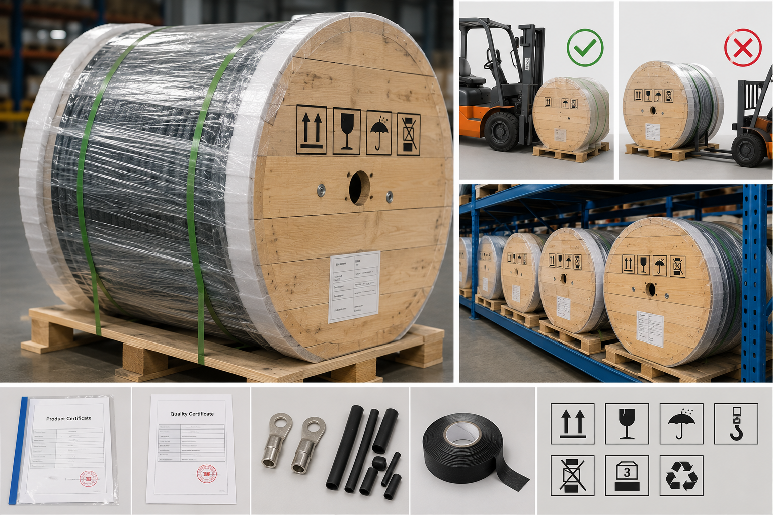
Flexible anodes are usually packed on reels. The outside is covered with foam film and waterproof plastic film.
The package should indicate the trademark, product name, model, manufacturer address, contact information, batch number, quantity, production date, forklift direction, forbidden forklift direction, stacking weight limit, no stacking mark, rotation direction, and other graphic signs. Other package marks may also be agreed upon by the supplier and buyer according to project requirements.
The items supplied with the product package should include the product certificate, quality certificate, relevant product accessories, spare parts, and other items agreed upon by the supplier and buyer.
During transportation and loading or unloading, the reel should be properly supported and fixed to prevent accidental rolling. When using a forklift, the allowed forklift direction and forbidden forklift direction should be observed to avoid damaging the flexible anode by inserting the forks from the wrong direction.
During storage and transportation, the product should avoid contact with toxic, harmful, corrosive, flammable, explosive, or other dangerous substances. The product should be stored in a safe, ventilated, dry, and cool place.
Ehisen can also discuss adjustments to packaging marks, product accessories, quality documents, and transportation fixing methods according to the customer’s project requirements. This helps meet different delivery and site management needs.

6. Installation and Use Requirements for Flexible Anodes
Product quality is important, but installation quality is also critical. If the installation method is incorrect, even a qualified flexible anode may not achieve the expected cathodic protection effect.
6.1 Inspection Before Installation
Before installation, the specification, quantity, appearance, dimensions, electrical continuity, factory inspection documents, and product certificates of the MMO/Ti flexible anode should be checked. Unqualified products should not be installed.
This step may seem simple, but it is very important for the project. It is recommended that the installation team prepare inspection records before installation to confirm that the model is consistent with the design, the appearance has no obvious damage, the documents are complete, and electrical continuity is normal.
6.2 Minimum Ambient Temperature for Installation
The minimum ambient temperature allowed for flexible anode installation depends on the internal cable sheath type. The following values may be used as reference:
| Internal Cable Sheath Type | Minimum Installation Temperature |
|---|---|
| Plastic insulation sheath | 0°C |
| Lead sheath steel tape armor | -7°C |
| PVC insulation and PVC sheath | -10°C |
| Rubber insulation and PVC sheath | -15°C |
| Rubber or PVC sheath | -15°C |
| Cold-resistant sheath | -20°C |
When the ambient temperature is lower than the corresponding requirement, the flexible anode may be moved indoors for preheating. The indoor temperature should be maintained at about 25°C, and open flames are strictly prohibited.
After the flexible anode temperature reaches and stays above the minimum installation temperature, installation may proceed. The installation time should preferably be controlled within 2 hours. The maximum ambient temperature at the installation site should preferably not exceed 40°C.
6.3 Dragging Should Be Avoided During Installation
MMO/Ti flexible anodes should not be dragged during installation. If the wrapping fabric is accidentally damaged and coke breeze filler leaks, the leakage point should be sealed before installation continues.
Forced dragging may damage the outer braided mesh, wrapping fabric, filler structure, nodes, or internal cable. Such damage may not be visible immediately on site, but it may affect long-term operation.
6.4 Minimum Distance Between Flexible Anodes, Protected Pipelines, and Nearby Facilities
Minimum Allowable Distance Between Flexible Anodes and Protected Pipelines or Nearby Facilities During Installation
| Nearby Facility | Parallel Installation — General Condition | Parallel Installation — Special Condition | Crossing Installation — General Condition | Crossing Installation — Special Condition |
|---|---|---|---|---|
| Protected buried pipeline | ≥300 mm and level with the bottom of the pipeline | ≥300 mm and increase the burial depth of the flexible anode | ≥300 mm, and the parallel pipeline protected by the flexible anode should be bonded to the crossing pipeline | Follow the general condition |
| Unprotected buried metal pipeline | If the flexible anode is parallel to the unprotected pipeline, the flexible anode and the unprotected pipeline should be located on different sides of the protected pipeline | Follow the general condition | ≥300 mm, and the flexible anode should be covered with an insulating isolation sleeve. The sleeve should extend at least 300 mm beyond both sides of the pipeline | Follow the general condition |
| Flexible anode | Flexible anodes installed close and parallel to each other should be placed on both sides of the protected pipeline | Follow the general condition | ≥100 mm, and at least one flexible anode should be covered with an insulating isolation sleeve. The sleeve should extend at least 100 mm beyond both sides of the flexible anode | Follow the general condition |
| Grounding electrode | If the flexible anode is parallel to the grounding electrode, the flexible anode and the grounding electrode should be located on different sides of the protected pipeline | If the grounding electrode and the flexible anode are on the same side of the protected pipeline, the grounding electrode should be covered with an insulating isolation sleeve, and the distance from the flexible anode should be ≥300 mm | ≥300 mm, and the grounding electrode should be covered with an insulating isolation sleeve. The covered length should be ≥300 mm | Follow the general condition |
| Control cable | ≥100 mm | Follow the general condition | ≥500 mm | Follow Note a |
| Power cable of 10 kV or below | ≥100 mm | Follow the general condition | ≥500 mm | Follow Note a |
| Power cable above 10 kV | ≥250 mm | ≥100 mm when separated by a partition or when the cable is installed in a conduit | ≥500 mm | Follow Note a |
| Main trunk of trees | ≥700 mm | Follow the general condition | — | — |
| Building foundation | ≥600 mm | Follow Note b | — | — |
| Overhead line pole of 1 kV or below | ≥1000 mm | Follow Note b | — | — |
| Overhead line pole above 1 kV | ≥4000 mm | Follow Note b | — | — |
| Highway | ≥1500 mm | Follow Note b | Follow Note c | Follow the general condition |
| Non-DC electrified railway track | ≥3000 mm | Follow the general condition | Follow Note c | Follow the general condition |
| DC electrified railway track | ≥10000 mm | Follow the general condition | Follow Note c | Follow the general condition |
Notes:
a. When separated by a partition or when the cable is installed in a conduit, the distance should be ≥250 mm.
b. Under special conditions, the distance may be appropriately reduced, but the reduction should not exceed 50%.
c. When crossing, the flexible anode should be replaced by a cable section. The cable should be installed inside a protective sleeve. The distance between the protective sleeve and the upper surface of the roadbed should be ≥1000 mm. The protective sleeve should have a drainage slope of not less than 1%. The protective sleeve should extend at least 500 mm beyond both sides of the roadbed. The distance between the joint of the flexible anode and the cable and the nearest end of the protective sleeve should be ≥1000 mm.
When a flexible anode is installed parallel to a protected pipeline, it should keep the required distance from the protected pipeline and nearby facilities. Common requirements include the following:
When installed parallel to the protected buried pipeline, the distance should be greater than or equal to 300 mm, and the flexible anode should be level with the bottom of the pipe. In special cases, the burial depth of the flexible anode may be increased.
When crossing the protected buried pipeline, the distance should be greater than or equal to 300 mm. The protected parallel pipeline and the crossing pipeline should be electrically bonded.
When installed parallel to an unprotected buried metal pipeline, the flexible anode should preferably be located on the opposite side of the protected pipeline from the unprotected pipeline.
When crossing an unprotected buried metal pipeline, the distance should be greater than or equal to 300 mm, and an insulating isolation sleeve should be used. The sleeve should extend at least 300 mm beyond both sides of the pipeline.
When flexible anodes are installed close and parallel to each other, they should be installed on both sides of the protected pipeline.
When flexible anodes cross each other, the distance should be greater than or equal to 100 mm. At least one flexible anode should be covered with an insulating isolation sleeve, and the sleeve should extend at least 100 mm beyond both sides of the flexible anode.
When installed parallel to a grounding electrode, the flexible anode should preferably be located on the opposite side of the protected pipeline from the grounding electrode. If the grounding electrode and flexible anode are on the same side of the protected pipeline, the grounding electrode should be covered with an insulating isolation sleeve, and the distance from the flexible anode should be greater than or equal to 300 mm.
When installed parallel to a control cable, the distance should be greater than or equal to 100 mm. When crossing a control cable, the distance should be greater than or equal to 500 mm.
When installed parallel to a power cable of 10 kV or below, the distance should be greater than or equal to 100 mm. When crossing such a cable, the distance should be greater than or equal to 500 mm.
When installed parallel to a power cable above 10 kV, the distance should be greater than or equal to 250 mm. If a partition is used or the cable is installed in a pipe, the distance may be considered not less than 100 mm. When crossing such a cable, the distance should be greater than or equal to 500 mm.
When installed parallel to a tree trunk, the distance should be greater than or equal to 700 mm.
When installed parallel to a building foundation, the distance should be greater than or equal to 600 mm.
When installed parallel to an overhead line pole of 1 kV or below, the distance should be greater than or equal to 1000 mm.
When installed parallel to an overhead line pole above 1 kV, the distance should be greater than or equal to 4000 mm.
When installed parallel to a highway, the distance should be greater than or equal to 1500 mm.
When installed parallel to a non-DC electrified railway track, the distance should be greater than or equal to 3000 mm.
When installed parallel to a DC electrified railway track, the distance should be greater than or equal to 10000 mm.
The main purpose of these distance requirements is to reduce current interference, insulation damage, third-party facility influence, and construction damage. Site design should not consider only the flexible anode itself. It should also consider nearby pipelines, cables, grounding electrodes, roads, railways, and building foundations.
6.5 Installation Notes for Pipeline Cathodic Protection
During installation, the flexible anode should remain relaxed in the anode bed and should have a certain amount of extra length. This helps prevent soil settlement from damaging the anode.
If the internal cable of the flexible anode is an armored cable, both ends of the steel tape armor layer should be grounded during installation.
When the flexible anode turns a corner and there is no parallel cable on the inside of the corner, the turning radius should be greater than or equal to 16D, where D is the outer diameter of the flexible anode. This requirement helps prevent structural damage caused by sharp bending.
When the flexible anode is installed on a slope of 20° to 50°, the installation inclination should not be greater than the natural slope of the terrain.
If the slope is less than or equal to 30°, the flexible anode should be fixed every 15 m. If the slope is greater than 30°, it should be fixed every 10 m. The fixing material should be insulating material.
During backfilling, the backfill soil should be screened to avoid damage to the flexible anode by hard lumps or sharp objects.
6.6 Installation Notes for Storage Tank Bottom Cathodic Protection
For storage tank bottom cathodic protection, flexible anodes may be arranged in concentric rings or in a serpentine layout. After the layout method and flexible anode spacing are determined, the protection area of all flexible anodes should cover the circular area of the external surface of the storage tank bottom.
During storage tank bottom installation, the following points should be noted:
The thickness of the sand cushion layer under the flexible anode should be greater than or equal to 50 mm.
The flexible anode and lead cable should remain naturally relaxed.
The cable should be protected from damage caused by tank bottom settlement.
During compaction of the sand cushion layer, tools and methods that may damage the flexible anode, such as vibrating rods, should not be used.
For storage tank bottom projects, the flexible anode installation area is usually difficult to repair after construction. Therefore, early design, product quality, installation method, and backfill protection are all very important.
7. Common Questions from Buyers
Question 1: Is a thicker flexible anode always better?
No. A larger MMO/Ti wire diameter usually allows a higher rated output current under the same design life, but it may also affect cost, bending requirements, and installation adaptability. The correct choice should be based on protection current demand, design life, soil environment, and installation space.
Question 2: How should we choose between FA and FApro?
For general projects, FA flexible anodes may be used. If the project is a concealed engineering project, future maintenance is difficult, or break point location is important, FApro break-detectable flexible anodes may be considered.
Question 3: What is the difference between α coating and β coating?
α usually refers to an iridium oxide-tantalum oxide coating, which is suitable for non-saline soil environments.
β usually refers to a ruthenium oxide-iridium oxide coating, which is suitable for saline soil or saline-alkali soil environments.
The actual selection should be based on project soil conditions.
Question 4: Why are connection nodes so important?
Connection nodes are the conductive connection points between the MMO/Ti wire and the internal cable. Node contact resistance, firmness, and sealing performance directly affect current transmission and long-term operating reliability.
Node problems are often hidden, and once the product is buried, repair becomes difficult. Therefore, node quality should be a key focus during procurement and acceptance.
Question 5: Why can prices be different if both products claim a 50-year design life?
Design life is related to MMO/Ti wire diameter, rated output current, coating system, node structure, cable sheath, outer materials, and inspection requirements.
Even if two products both claim a 50-year design life, their actual configurations may be different if the output current conditions are different. Buyers should ask the supplier to explain the rated output current corresponding to the claimed design life.
Question 6: Can flexible anodes be installed directly in low-temperature environments?
Not always. The minimum installation temperature depends on the internal cable sheath type. For example, plastic insulation sheath is suitable for installation at 0°C or above, while cold-resistant sheath may be suitable down to -20°C.
If the ambient temperature is lower than the allowed temperature, indoor preheating should be carried out, and open flames are strictly prohibited.
Question 7: Can flexible anodes be dragged during installation?
No. Dragging may damage the outer structure, filler, nodes, or internal cable. If the outer layer is damaged and coke breeze filler leaks, the leakage point should be sealed before installation continues.
Question 8: What information should customers provide for storage tank bottom projects?
Customers are advised to provide tank diameter or radius, protection current density, design life, planned layout method, site installation space, sand cushion condition, groundwater situation, and acceptance requirements. This information helps calculate flexible anode length, output current, and layout spacing.
Question 9: What should be checked first after receiving flexible anodes?
Buyers should first check the model, quantity, appearance, outer diameter, linear density, product marks, certificate, quality documents, and electrical continuity.
For large projects, node contact resistance, sealing performance, bending radius, and operating performance test requirements should also be reviewed.

8. What Information Should Buyers Confirm Before Ordering Flexible Anodes?
To avoid unclear selection, acceptance disputes, or installation problems, buyers are advised to provide and confirm the following information during inquiry:
Project application: buried pipeline, station area, airport apron pipe network, or storage tank bottom.
Soil environment: whether the soil is saline, whether the site is saline-alkali land, and groundwater conditions.
Environmental temperature: minimum installation temperature and long-term operating temperature.
Whether there is termite or other biological damage risk.
Required design life.
Protection current density or total current demand.
Whether ordinary flexible anode or break-detectable flexible anode is required.
MMO/Ti wire diameter requirement.
Cable copper core cross-sectional area requirement.
Coating type requirement.
Length per reel or sectional length.
Whether joints are allowed and the allowed number of joints.
Node spacing and node resistance requirements.
Inspection items and quality document requirements.
Packaging, transportation, and site installation requirements.
The more complete the information is, the easier it is for the supplier to provide a suitable product solution. For engineering products, the value of a professional supplier is not only to provide products, but also to help customers match the product model, structure, performance, and site conditions.
9. Conclusion: How to Judge Whether a Flexible Anode Is Worth Purchasing
To evaluate the quality of an MMO/Ti flexible anode, buyers should not only check whether the appearance is complete, and they should not choose only based on the lowest price. A reliable flexible anode should meet the following requirements:
The product structure should be clear. The supplier should be able to explain the configuration of the MMO/Ti wire, internal cable, coke breeze filler, wrapping fabric, wear-resistant braided mesh, and connection nodes.
The model expression should be clear. The MMO/Ti wire diameter, cable copper core cross-sectional area, and coating type should be clearly identified.
The appearance and dimensions should meet the requirements. Outer diameter, linear density, braided mesh integrity, and filler condition should be inspectable.
The MMO/Ti wire coating should match the soil environment. Coating adhesion and coating thickness should be verifiable.
The internal cable sheath should be suitable for the project environment, including temperature, groundwater, soil corrosion, and biological damage risks.
The connection nodes should be reliable, with low contact resistance and good waterproof sealing performance.
The design life should correspond clearly to rated output current. It should not be a vague service life statement.
The operating performance should be reasonably verified. After continuous operation, current output, node connection, and sealing condition should remain stable.
Packaging, transportation, storage, and installation requirements should be clear to reduce the risk of site damage.
The supplier should be able to support model selection, processing customization, and quality documents according to the project environment and customer requirements.
Ehisen is a supplier of precious metal coated titanium anode products. We can provide common MMO/Ti flexible anode models and support customization according to different soil conditions, design life requirements, output current, installation methods, and acceptance requirements.
If you are selecting flexible anodes for buried pipelines, station areas, airport apron pipe networks, or storage tank bottom cathodic protection projects, you are welcome to send your project parameters, drawings, or technical requirements to Ehisen. Our team will help review a suitable product solution and provide quotation support.