At Ehisen, we prioritize strict dimensional and quality inspection of titanium raw materials before processing. Accurate control of material composition, surface condition, and dimensional tolerance directly influences coating adhesion, product deformation, and long-term stability. By ensuring each substrate meets precise specifications, we help prevent defects and support reliable performance and easy installation for your titanium anode applications.
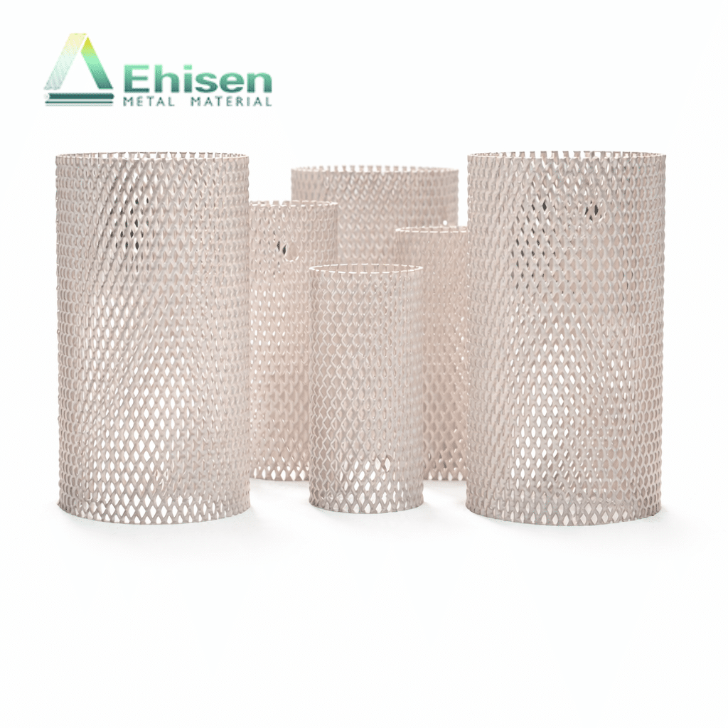
Our platinum plated electrodes are available with either electroplated or brush-coated finishes, offering excellent conductivity and corrosion resistance. Electroplating provides a uniform and thin coating ideal for precise applications, while brush coating allows for thicker layers in selected areas. We offer customized processing to meet your specific technical and dimensional requirements.
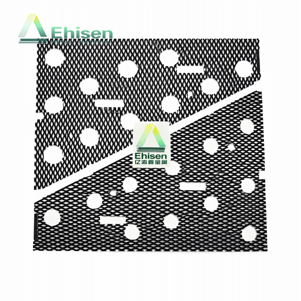
Our MMO titanium mesh is available with a range of mixed metal oxide coatings to suit various industrial applications, including water treatment, electroplating, and cathodic protection. Different ratios of precious metals such as ruthenium, iridium, and tantalum affect both performance and cost. We offer custom formulations based on your needs or provide recommendations backed by our technical expertise.
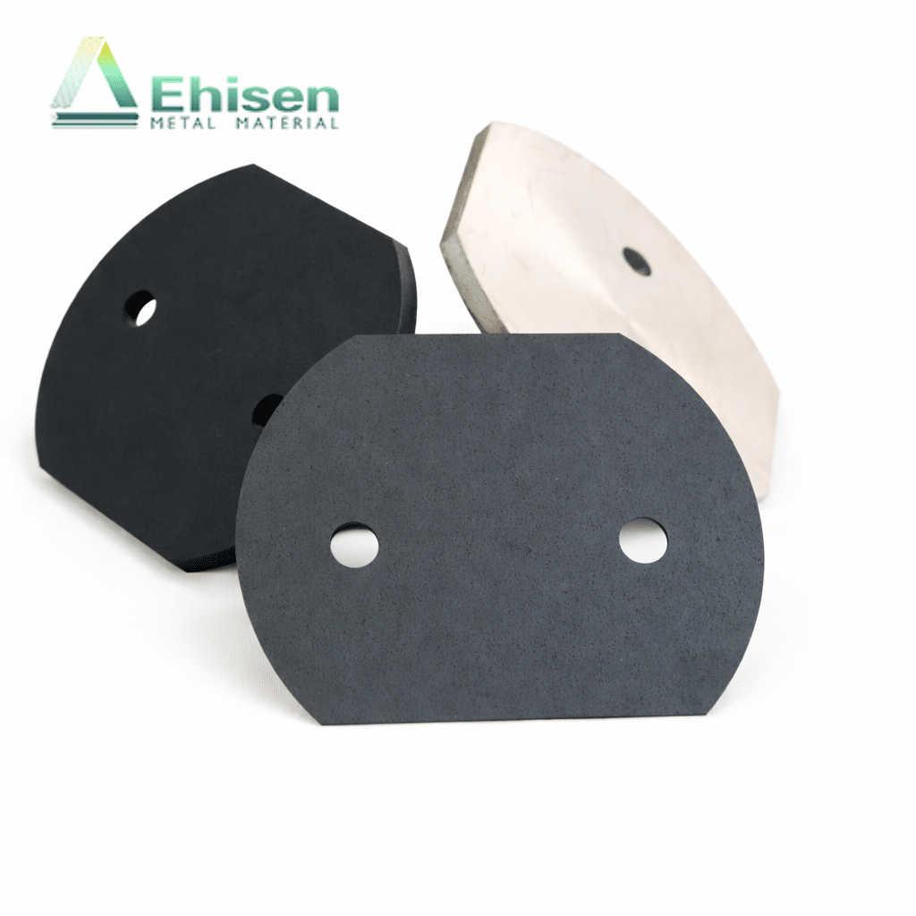
Backed by years of production and research, our dimensionally stable electrodes offer low working voltage, long service life, and exceptional corrosion resistance. Made from titanium, they are lightweight, easy to process, and do not dissolve during use. The substrate can be reused multiple times, making them a durable and efficient solution for various electrochemical applications.
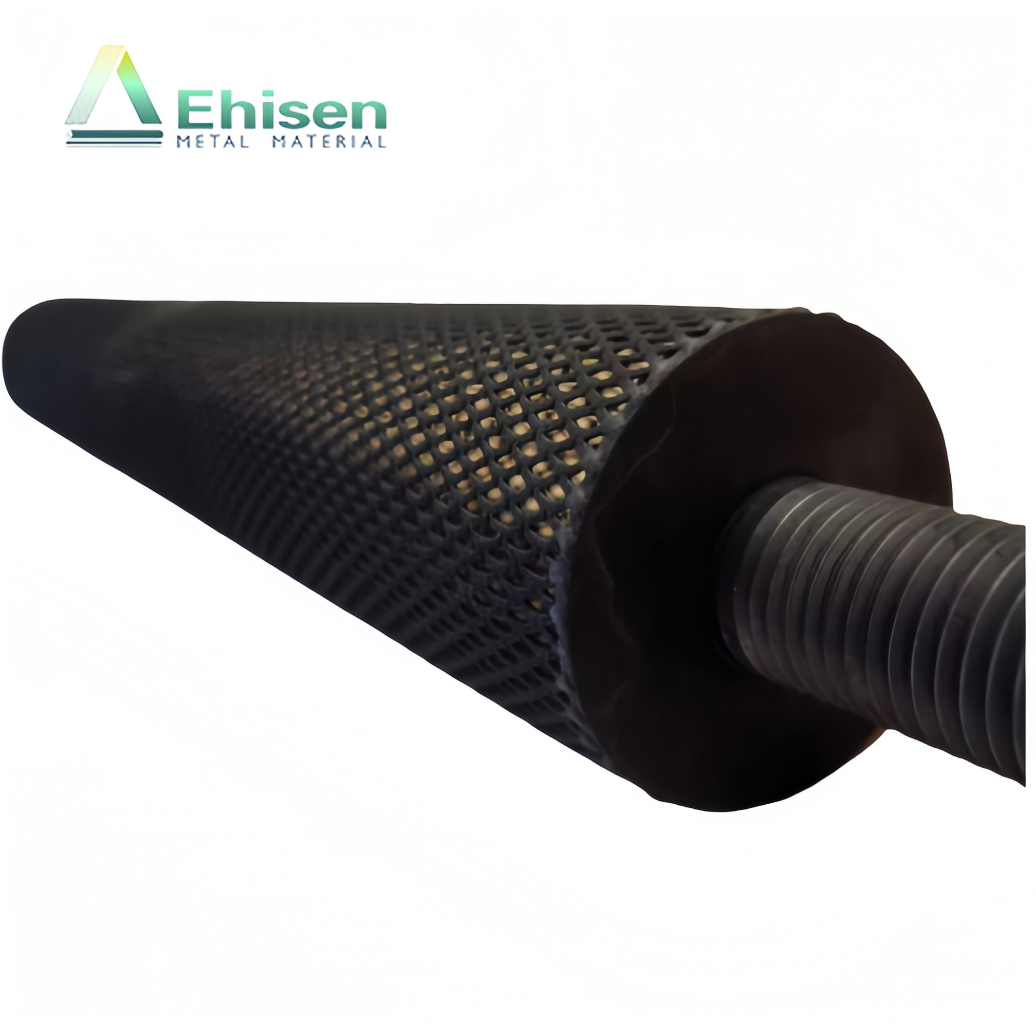
Our mixed metal oxide (MMO) coatings are specially formulated for brush-coated titanium anodes, using combinations such as ruthenium–iridium, iridium–tantalum, and other optional elements like tin, antimony, or silver based on application needs. We customize coatings according to your requirements and collaborate with you through testing and optimization to ensure the best electrode performance.

At Ehisen, we place product quality at the core of every project. Through advanced inspection, strict verification, and certified testing methods, we ensure every titanium anode meets the highest performance standards. Here’s why our clients trust us for reliable quality assurance:
We carry out detailed inspections on titanium substrates before processing, including chemical composition, dimensional accuracy, and surface condition checks. This ensures coating adhesion, product stability, and long-term reliability from the very beginning.
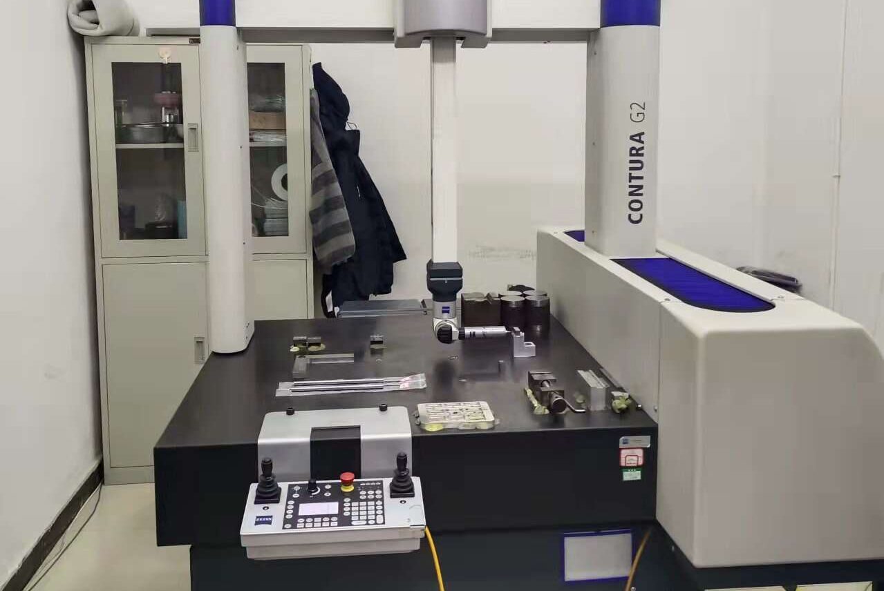
Equipped with coordinate measuring machines (CMM), we can precisely inspect both simple and complex products. Whether for large components or intricate details, our dimensional checks guarantee that every product fits its intended application with accuracy.
Our in-house laboratory is equipped with spectrometers to analyze titanium substrate composition. In addition, two nearby national-level metal testing centers provide independent re-examination and official reports, ensuring reliable data and trusted verification.



Technical Director of Ehisen


CEO of Ehisen
We conduct comprehensive evaluations of coating performance, including thickness measurement, uniformity checks, and analysis of precious metal content using advanced testing equipment. By monitoring these critical parameters, we ensure strong bonding between the coating and the titanium substrate, stable electrochemical behavior in service, and consistent long-term performance across different anode types and applications.
All of our inspection tools are regularly calibrated at a local, accredited measurement center with national certification. This process guarantees the accuracy, reliability, and traceability of every reading, whether related to dimensions, surface condition, or coating thickness. By maintaining strict control of measuring instruments, we provide customers with trustworthy data and dependable quality assurance.
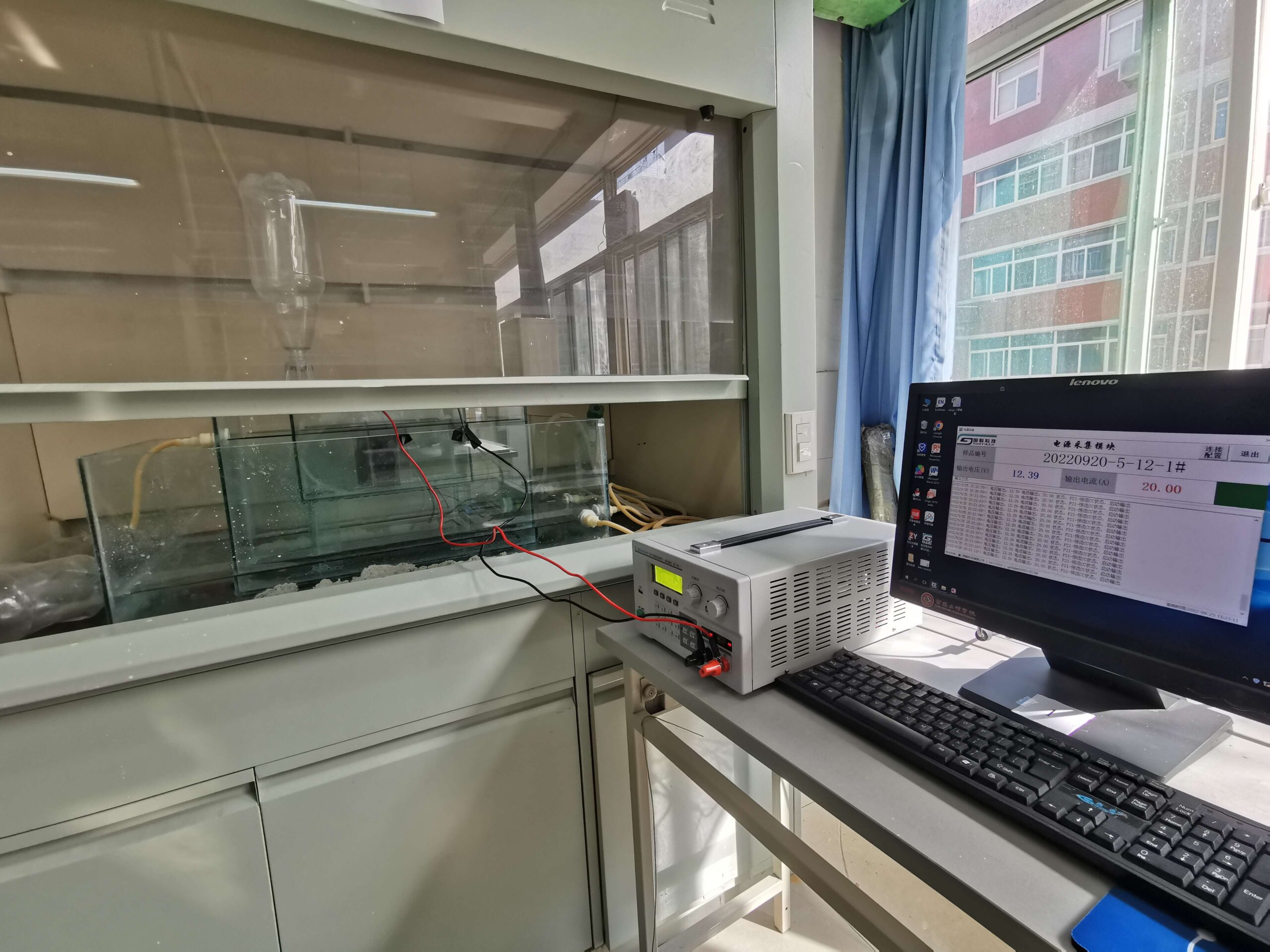
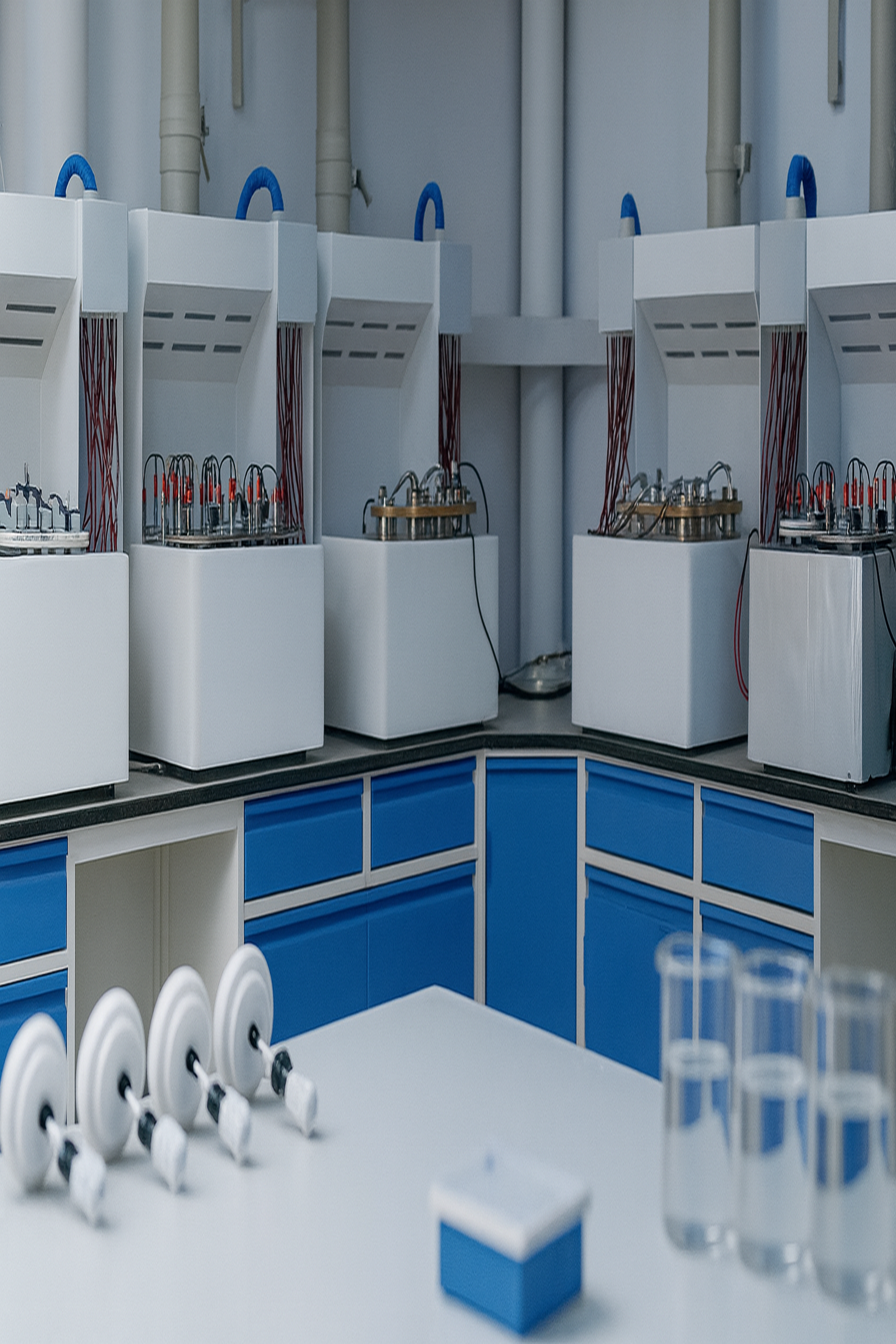
In addition to routine inspections, Ehisen applies reinforced enterprise-level testing standards to simulate real operating conditions and extended service life. Through accelerated aging tests and performance monitoring, we verify that our titanium anodes can withstand demanding environments and maintain their efficiency over time. This proactive approach ensures durability, reduces risk in customer applications, and builds confidence in long-term use.
For procurement professionals, a clear understanding of titanium anode quality inspection is essential. Substrate checks such as composition analysis, dimensional measurement, and surface evaluation directly determine coating adhesion, product stability, and long-term performance. At Ehisen, we apply strict in-process inspections to ensure raw materials meet specifications before coating and assembly. This thorough approach not only guarantees reliable product performance but also helps procurement teams assess quality consistency, compare supplier standards, and make confident sourcing decisions with reduced risk.
Goal: Find and fix problems right after cutting, welding, and machining—so defects don’t enter coating and sintering (which would hurt adhesion, lifetime, and energy performance).
After cutting: length, width, thickness (or wire Ø / tube wall), hole Ø & pitch, edge distance; check burrs/scratches on cut edges.
After welding/assembly: weld position & size (fillet height, bead width, hole pitch), flatness/squareness/warp, weld appearance & color.
After machining: fit dimensions & GD&T (flatness, concentricity), deburring/chamfer, surface roughness (Ra).
| Item | Focus area | Method/tools | Release focus |
|---|---|---|---|
| Dimensions | L/W/T, hole Ø & pitch, flange/ear location | Calipers/micrometers, projector/vision, CMM | Meet drawing tolerance; attach CMM/vision screenshots for critical features |
| Surface | Cut edges, bends, clamping marks, functional faces | Visual + low-angle light, touch, roughness tester | No deep scratches/crush marks/scale; Ra meets spec; sharp edges chamfered (e.g., R0.2–R0.5) |
| Welds | Bus bar, ears, flanges, mesh-to-plate/tube joints | Visual (shape/splash/undercut), color, dye penetrant (PT) if needed | Silver to light straw is OK; blue/purple/black = over-heat/poor shielding |
| Burrs / micro-cracks | Cut holes, edges, mesh cut ends | Visual + glove wipe, magnifier | No burrs or roll-overs; holes not sharp to touch; mesh ends tidy |
Tip — color = fast signal. Blue/purple/black weld color usually means over-heat or poor argon shielding. If not corrected, coating adhesion and lifetime will suffer.
Why it matters: Deep scratches, micro-cracks, oxide scale, and oil/salt leave weak spots. Coating can blister or peel from those places.
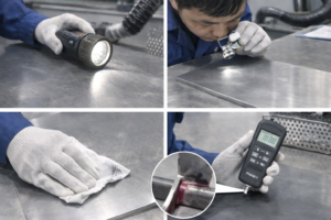
How we check
Visual + low-angle light (30–45°, ≥500–1000 lux) to reveal lines/waves.
10× magnifier / portable microscope for tiny cracks/pits.
White glove/paper wipe to find loose oxide or dirt (black mark = risk).
Roughness tester (Ra) per drawing or functional target.
PT (dye penetrant) on crack-prone zones (weld toes, bend roots, hole rims).
After any grinding, re-check thickness/flatness so you don’t over-remove material.
Quick decision table
| Defect | Quick ID | Impact | Release rule (guide) | On-site fix | If over limit |
|---|---|---|---|---|---|
| Scratch/gouge | Clear line under low-angle light; continuous groove at 10× | Stress riser → blister/peel | Must be fully removed by light grind + acid clean | P400→P600/800 with grain → degrease → optional acid activate → re-check Ra/looks | Too deep or dimension affected → rework/replace |
| Micro-crack / hot crack | Hard to see; PT shows line indication | Through-defect → early failure | Zero tolerance (functional faces/weld areas) | Local groove out → re-weld (argon both sides) → blend → PT re-check | If it spreads or weakens part → reject/re-make |
| Oxide scale / heat tint | Blue/purple/black; black on wipe | Hard to remove fully → weak adhesion | Not allowed on functional/weld areas | Grind to bright metal → degrease → argon-shield re-weld or light grind HAZ → acid/ light blast → re-check | Large area or repeated → trace weld params; rework to base if needed |
| Pits/inclusions pull-out | Random pits at 10× | Thin spots / pinholes | Not allowed as clusters; isolated must be removable by prep | Light blend → mild acid etch → re-check | Deep or many → rework/reject |
| Oil/salt/hand marks | Gray film on wipe; poor water wetting | Craters/fisheyes | Not allowed | Acetone/IPA degrease → DI rinse → low-temp dry → white paper re-check | If repeated → audit tools/gloves/area |
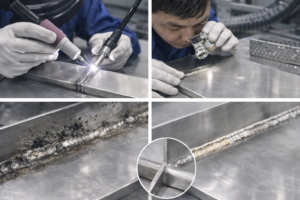
Poor shielding / over-heat (no back-purge, low flow, air drafts) → thick oxide / alpha-case that acid/blast can’t fully remove → weak adhesion, life scatter.
Shape defects (undercut, porosity, slag, heavy splash) → thin-coat or sharp edges → higher voltage, local corrosion.
Weld distortion → flatness/hole-pitch drift → unstable fixturing → uneven coating, bare edges, runs.
Good weld look: Smooth, even bead; silver–light straw color; no undercut/porosity/linked holes/splash; back side also protected.
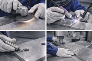
Dimensional out-of-tolerance / hole pitch off: re-machine or cold-straighten; bush/ream with approval.
Heat tint (blue/purple/black): grind to bright metal → degrease → re-weld with front & back argon purge → acid or light blast → re-check PT/visual.
Weld defects (undercut/porosity/slag): remove by local grinding → re-weld → re-inspect; many defects → rework to base.
Burrs/sharp edges: chamfer/deburr tools or belts; for mesh, control cut direction to avoid spikes.
Distortion: cold press or controlled heat straightening; re-check flatness/straightness.
Welding procedure & skills: Use WPS/PQR, qualify welders; ≥99.99% argon, front + back purge, log current/voltage/speed/flow.
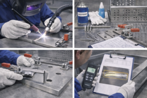
Cleanliness: Acetone degrease before weld; dry; clean gloves/fixtures; no touch on functional faces.
Fixtures & stops: Unified datums, hard stops, clamp points; check key hole pitch with pins to limit distortion.
In-process control: First-Article Inspection (FAI), in-process sampling, stop-line for abnormalities; after welding, cover to protect while cooling.
Records & traceability: Save photos and readings (dimensions, weld, surface). For key lots, add PT report and weld parameter log—helps link to coating quality later.
Short term: pinholes/craters/runs in coating, higher initial voltage.
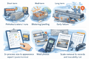
Mid term: local blister/peel, potential drift, higher energy use.
Long term: early failure, line stops; re-make cost is much higher than early repair.
In-process size & appearance report (points/nominal/measured/judgement, tool IDs, environment).
Weld photos (with color reference) and PT report if used.
Straightening/re-weld/scale-removal repair records and re-inspection results.
Traceability list: process timestamps, operator, fixture/equipment IDs—to support coating/sintering release.
Goal: Find and fix problems right after cutting, welding, and machining—so defects don’t enter coating and sintering (which would hurt adhesion, lifetime, and energy performance).
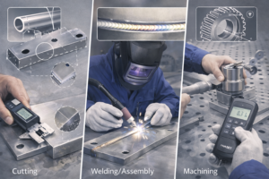
After cutting: length, width, thickness (or wire Ø / tube wall), hole Ø & pitch, edge distance; check burrs/scratches on cut edges.
After welding/assembly: weld position & size (fillet height, bead width, hole pitch), flatness/squareness/warp, weld appearance & color.
After machining: fit dimensions & GD&T (flatness, concentricity), deburring/chamfer, surface roughness (Ra).
| Item | Focus area | Method/tools | Release focus |
|---|---|---|---|
| Dimensions | L/W/T, hole Ø & pitch, flange/ear location | Calipers/micrometers, projector/vision, CMM | Meet drawing tolerance; attach CMM/vision screenshots for critical features |
| Surface | Cut edges, bends, clamping marks, functional faces | Visual + low-angle light, touch, roughness tester | No deep scratches/crush marks/scale; Ra meets spec; sharp edges chamfered (e.g., R0.2–R0.5) |
| Welds | Bus bar, ears, flanges, mesh-to-plate/tube joints | Visual (shape/splash/undercut), color, dye penetrant (PT) if needed | Silver to light straw is OK; blue/purple/black = over-heat/poor shielding |
| Burrs / micro-cracks | Cut holes, edges, mesh cut ends | Visual + glove wipe, magnifier | No burrs or roll-overs; holes not sharp to touch; mesh ends tidy |
Tip — color = fast signal. Blue/purple/black weld color usually means over-heat or poor argon shielding. If not corrected, coating adhesion and lifetime will suffer.
Why it matters: Deep scratches, micro-cracks, oxide scale, and oil/salt leave weak spots. Coating can blister or peel from those places.
How we check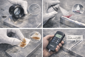
Visual + low-angle light (30–45°, ≥500–1000 lux) to reveal lines/waves.
10× magnifier / portable microscope for tiny cracks/pits.
White glove/paper wipe to find loose oxide or dirt (black mark = risk).
Roughness tester (Ra) per drawing or functional target.
PT (dye penetrant) on crack-prone zones (weld toes, bend roots, hole rims).
After any grinding, re-check thickness/flatness so you don’t over-remove material.
Quick decision table
| Defect | Quick ID | Impact | Release rule (guide) | On-site fix | If over limit |
|---|---|---|---|---|---|
| Scratch/gouge | Clear line under low-angle light; continuous groove at 10× | Stress riser → blister/peel | Must be fully removed by light grind + acid clean | P400→P600/800 with grain → degrease → optional acid activate → re-check Ra/looks | Too deep or dimension affected → rework/replace |
| Micro-crack / hot crack | Hard to see; PT shows line indication | Through-defect → early failure | Zero tolerance (functional faces/weld areas) | Local groove out → re-weld (argon both sides) → blend → PT re-check | If it spreads or weakens part → reject/re-make |
| Oxide scale / heat tint | Blue/purple/black; black on wipe | Hard to remove fully → weak adhesion | Not allowed on functional/weld areas | Grind to bright metal → degrease → argon-shield re-weld or light grind HAZ → acid/ light blast → re-check | Large area or repeated → trace weld params; rework to base if needed |
| Pits/inclusions pull-out | Random pits at 10× | Thin spots / pinholes | Not allowed as clusters; isolated must be removable by prep | Light blend → mild acid etch → re-check | Deep or many → rework/reject |
| Oil/salt/hand marks | Gray film on wipe; poor water wetting | Craters/fisheyes | Not allowed | Acetone/IPA degrease → DI rinse → low-temp dry → white paper re-check | If repeated → audit tools/gloves/area |
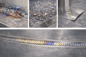
Poor shielding / over-heat (no back-purge, low flow, air drafts) → thick oxide / alpha-case that acid/blast can’t fully remove → weak adhesion, life scatter.
Shape defects (undercut, porosity, slag, heavy splash) → thin-coat or sharp edges → higher voltage, local corrosion.
Weld distortion → flatness/hole-pitch drift → unstable fixturing → uneven coating, bare edges, runs.
Good weld look: Smooth, even bead; silver–light straw color; no undercut/porosity/linked holes/splash; back side also protected.
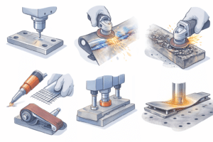
Dimensional out-of-tolerance / hole pitch off: re-machine or cold-straighten; bush/ream with approval.
Heat tint (blue/purple/black): grind to bright metal → degrease → re-weld with front & back argon purge → acid or light blast → re-check PT/visual.
Weld defects (undercut/porosity/slag): remove by local grinding → re-weld → re-inspect; many defects → rework to base.
Burrs/sharp edges: chamfer/deburr tools or belts; for mesh, control cut direction to avoid spikes.
Distortion: cold press or controlled heat straightening; re-check flatness/straightness.
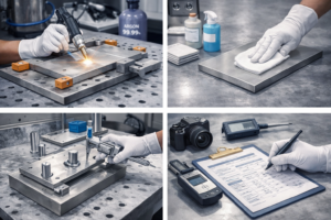
Welding procedure & skills: Use WPS/PQR, qualify welders; ≥99.99% argon, front + back purge, log current/voltage/speed/flow.
Cleanliness: Acetone degrease before weld; dry; clean gloves/fixtures; no touch on functional faces.
Fixtures & stops: Unified datums, hard stops, clamp points; check key hole pitch with pins to limit distortion.
In-process control: First-Article Inspection (FAI), in-process sampling, stop-line for abnormalities; after welding, cover to protect while cooling.
Records & traceability: Save photos and readings (dimensions, weld, surface). For key lots, add PT report and weld parameter log—helps link to coating quality later.
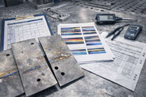
Short term: pinholes/craters/runs in coating, higher initial voltage.
Mid term: local blister/peel, potential drift, higher energy use.
Long term: early failure, line stops; re-make cost is much higher than early repair.
In-process size & appearance report (points/nominal/measured/judgement, tool IDs, environment).
Weld photos (with color reference) and PT report if used.
Straightening/re-weld/scale-removal repair records and re-inspection results.
Traceability list: process timestamps, operator, fixture/equipment IDs—to support coating/sintering release.
Goal: After coating (and any heat treatment), quickly confirm surface quality, loading uniformity, crystal structure, and integrity of the active layer so batches can be released with confidence and long life.
Fast on-site checks (100% or sampling):
Visual + low-angle light: look for runs, pinholes, fisheyes, orange peel, or bare edges/holes.
White filter-paper wipe: no obvious black mark = good bond; black mark = adhesion risk (recheck drying/temperature/cooling).
Surface roughness (Ra) & uniform look: no sudden texture changes on functional faces.
Four-point probe (sheet resistance): multiple points; large scatter hints at density/phase issues.
Cross-section check (cut piece or fracture): layer stack and total thickness match the process card.
Helpful tools:
Optical microscope (50–200×), SEM (Scanning Electron Microscope) for surface detail, EDS (energy-dispersive X-ray) maps for Ru/Ir/Ta distribution. Cross-section made by mechanical polish or FIB when needed.
Release focus:
Add XRF uniformity heatmap (see C) + photos of edges/holes/bends. Any black-wipe, clusters of pinholes, or obvious bare edges → evaluate rework (light grind + touch-up + re-fire, or strip & recoat).
Fast on-site checks: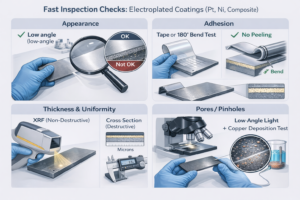
Appearance: even color, no burnt areas, no rough “sand” or stripes; no missed spots in blind zones/holes.
Adhesion: simple tape test or 180° bend per your limit; cross-hatch if needed.
Thickness & uniformity: XRF thickness (non-destructive) plus cross-section (destructive) for confirmation.
Pores/pinholes: optical + low-angle light; optional copper deposition test to reveal pores.
Notes:
Burnt/rough deposits = excessive local current or organic contamination. Thick plating can trap hydrogen—do a low-temp de-embrittlement bake and recheck.
| Purpose | Method | What you learn | Sampling / caution |
|---|---|---|---|
| Surface morphology | Optical, SEM | Particles, pores, runs, pinholes | Sample center/edge/holes/bends; non-conductive spots need Au/C coating; avoid beam damage |
| Areal loading & uniformity (g/m²) | XRF point/area scan | Ru/Ir/Ta/Pt loading, thickness, heatmap | Do blank-Ti correction & standard calibration; set tolerance (e.g., ±10%) and report pass rate |
| Element distribution | EDS mapping (with SEM) | Uniformity / segregation | Watch peak overlaps; don’t misread Ti substrate as “thin coat” |
| Valence / surface chemistry | XPS | Ru(IV)/Ir(IV), adsorbed species | Surface only (few nm); light clean before vacuum; include peak-fit and binding-energy refs |
| Crystal phase / structure | XRD (grazing incidence is best) | Rutile/anatase, solid solution, grain trend | Thin films give weak peaks; report peak positions, FWHM, and phase % if quantified |
| Active nanocrystals | TEM/SAED (optional) | Grain size, boundaries | FIB lamella; higher cost—use for DOE or failure analysis |
| Layer stack | Cross-section SEM/optical | Total thickness, transition/barrier layers | Embed & polish; label scale and layer names |
| Electrical | Four-point probe / local potential map | Surface resistance & scatter | Keep probe spacing/pressure constant; log temperature & direction |
| Electrochemical quick check | Polarization / EIS | Initial activity & transport | Highly condition-dependent—always log electrolyte, pH, temperature |
Report tips (what we can include):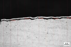
XRF: target vs. actual, uniformity stats, heatmap with min/max points.
SEM/EDS: representative surface & cross-section images (edge/hole/bend), EDS maps.
XRD: diffraction plot, phase table, peak width/grain estimate (Scherrer).
XPS: fitted peaks, valence ratios, calibration (e.g., C 1s = 284.8 eV).
4-point/EIS: point layout, mean & stdev, test conditions.
| Symptom | Likely cause | Quick fix (this lot) | Prevent next lot |
|---|---|---|---|
| Black mark on wipe / poor adhesion | Incomplete drying; low oxidation temp; recoated while warm | Light grind → thin touch-up → re-fire; severe → strip & recoat | Enforce complete drying; force-cool to room temp between passes |
| Pinholes / fisheyes | Surface contamination; solvent residue; dust | Local recoat and re-fire | Strict degrease & clean air; control wet-film limit |
| Uneven loading (XRF heatmap blotchy) | Edge/hole under-weighting; unstable brush/spray path | Add edge/hole touch-up; refine path | Fixed routes + fixtures; mark thickened zones on drawing |
| Abnormal XRD / bluish tint | Over-temp or over-soak; door-zone over-comp | Redo last 1–2 passes at correct window | Use zoned control + door compensation; TC mapping |
| High organics on XPS | Handling/transport contamination | Gentle plasma clean then re-run | Sealed transfer; low-temp dry before test |
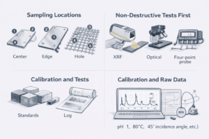
Where to sample: at least center / edge / hole / bend per part; for mesh, also at wire intersections.
Non-destructive first: XRF, optical, four-point probe; keep destructive (cross-section, TEM) for failure analysis or special studies.
Calibration = credibility: include standards and calibration logs for XRF/XPS/XRD; keep angles and settings consistent across lots.
Keep raw data: store original spectra/images and list all test conditions (electrolyte, pH, temperature, incidence angle, etc.).
COA: appearance, target/actual loading, uniformity stats, key electrical/electrochemical data.
Characterization pack: XRF heatmap, XRD plot, SEM/EDS (surface + cross-section), XPS summary, four-point statistics, cross-section thickness.
Traceability: per-pass drying/sintering temps & times, TC map, cooling records, marked edge/hole weighting routes.
Bottom line: Combine fast on-site checks with smart lab tests. That’s how you get coatings that are uniform, correctly phased, and well bonded—and electrodes that hold voltage and life in real service.
Bottom line: The service life of a titanium anode is a key performance metric. Real-life tests are often too slow, costly, or hard to reproduce. ALT uses harsher but controlled conditions to reveal issues faster—so you can judge quality, compare designs, and approve production with confidence.
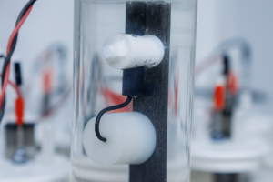
Real-life takes too long: months or years of operation to see failure trends.
Hard to copy the site exactly: electrolytes, impurities, temperature, and flow can vary—labs can’t mirror all of it.
Fast screening: when introducing a new recipe/process/supplier, you need a quick “go/no-go.”
Quality gate: ALT exposes early weaknesses (poor adhesion, unstable phase/valence, uneven loading, weak weld areas).
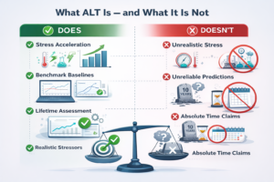
Applies controlled and traceable stress acceleration
Increases operating stress in a scientifically controlled way—such as higher current density, elevated temperature, increased chloride/acid concentration, or adjusted duty cycles—while preserving the same failure mechanisms seen in real applications.
Generates comparable, data-driven outputs
Continuously records key indicators such as voltage–time curves, polarization behavior, and/or EIS data, enabling direct comparison with baseline performance and predefined targets.
Provides relative lifetime validation
Uses acceleration factors to evaluate whether a product is likely to meet its intended lifetime requirements under real operating conditions.
Does not rely on unrealistic extreme conditions
Avoids excessive stress levels that would introduce new failure mechanisms, as such data would no longer represent actual field behavior.
Does not claim absolute service life on its own
ALT establishes strong performance correlation and degradation trends, but it is not a direct calendar-life prediction tool. Final lifetime assessments require correlation with real operating data.

Faster prediction: results in days/weeks, not months.
Weak-spot discovery: easier to see interlayer bond issues, phase errors, thin edges/holes, oxidation window drift, etc.
Process tuning: data to optimize loading (g/m²), pass count, zoned temperature control, inter-pass cooling, edge/hole weighting.
Lower risk, lower cost: avoid ramping bad designs into production.
Mechanism shift: too much stress can trigger failures unlike the field.
Correlation needs building: use sample → pilot → production to calibrate acceleration factors and limits for your line.
Statistics matter: apply sensible AQL / sample sizes to avoid one-off misreads.
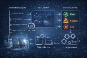
Tiered stress matrix: light / medium / heavy acceleration around your window—chosen to avoid mechanism changes.
Traceable records: full logs for electrolyte, temperature, pH, halides, J/duty, plus voltage–time curves (and polarization/EIS if needed).
Clear judgments: compare to baseline & historical good lots; provide pass / caution / fail thresholds and actions.
Close-the-loop advice: if not meeting targets, propose concrete tweaks (edge weighting, pass/loading adjustment, zone control & cooling cadence).
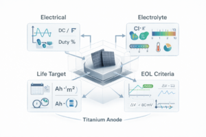
Current density & frequency (DC or pulsed, duty%).
Electrolyte basics (Cl⁻/F⁻ present? pH? temperature range?).
Life target (calendar months/years, Ah·m⁻², or accelerated hours).
Voltage-rise limit & end-of-life rule (e.g., ΔV ≤ 80 mV = pass).
Next sections will cover: 2.2 ALT test conditions & protocol, 2.3 How electrolyte factors affect ALT, and 2.4 How to choose electrolyte factors for ALT.
Key point: There is no single international standard for electrolyte factors in Accelerated Life Tests (ALT) on titanium anodes. The list below summarizes typical conditions reported in the literature.
On top of that, our website’s QC page hosts Ehisen’s internal ALT manuals for different applications. We can align a unified ALT spec with you so every batch is tested under the same environment, making results comparable and quality easier to control:
👉 https://ehisenelectrode.com/quality-control/
Variables most often adjusted: electrolyte composition/concentration, temperature, pH, current density (J)—commonly acidic or sulfate media to accelerate OER/CER failure mechanisms.
| Electrolyte (conc.) | Temp | Current density (J) | Note |
|---|---|---|---|
| H₂SO₄ 4 mol/L | 60 °C | 4 A/cm² | — |
| H₂SO₄ 0.5 mol/L | 25 °C | 2 A/cm² | — |
| Na₂SO₄ 1 mol/L | 60 °C | 2 A/cm² | — |
| H₂SO₄ 1 mol/L | 80 °C | 4 A/cm² | — |
| Na₂SO₄ 1 mol/L | 60 °C | 3 A/cm² | pH adjusted to 1.2 with H₂SO₄ |
| Na₂SO₄ 0.176 mol/L | 50 °C | 2 A/cm² | With/without ~0.454 mol/L p-benzoquinone (or sulfonate) |
| H₂SO₄ 30 wt% | 80 °C | 5 A/cm² | Strong stress |
| H₂SO₄ 0.5 mol/L | 25 °C | 1 A/cm² | Mild stress |
| H₂SO₄ 30 wt% | 30–40 °C | 4 A/cm² | — |
| H₂SO₄ 30 wt% | 70 °C | 2 A/cm² | — |
| HClO₄ 1 mol/L | 50 °C | 0.8 A/cm² | Perchloric system—follow strict safety rules |
| H₂SO₄ 0.5 mol/L | 30 °C | 2 A/cm² | — |
| H₂SO₄ 0.5 mol/L | 50 °C | 2 A/cm² | — |
| H₂SO₄ 0.5 mol/L | 30 °C | 3 A/cm² | — |
| H₂SO₄ 1 mol/L | 40 °C | 4 A/cm² | — |
Takeaway: the spread is wide, confirming there’s no single global standard—which is why agreeing a unified ALT spec with you up front is so useful.
We recommend setting three tiers (around your operating window) and locking the test factors to keep results comparable and traceable.
Factors to fix in the agreement:
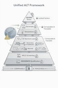
Electrolyte: composition/concentration (Cl⁻/F⁻/organics or not), pH.
Temperature: setpoint & tolerance (± °C); circulation or static.
Electrical load: J (A/cm²), DC or pulsed (frequency/duty).
Hydraulics & geometry: stirring/flow, electrode gap, counter-electrode material, area ratio.
Pass/fail: ΔV threshold (e.g., 50–100 mV) or minimum hours / Ah·m⁻².
Statistics: ≥ 3 pcs per tier; report mean, SD, and outlier rule.
Records: electrolyte, temperature, pH, J/duty; voltage–time curves (add polarization/EIS if needed).
Post-test analysis (optional): SEM/EDS, XRD, XPS, cross-section at failure sites to confirm mechanism.
Three-tier example (easy to negotiate):
Mild (Screening): 0.5 mol/L H₂SO₄, 25–30 °C, 1–2 A/cm² (DC)
Moderate (Qualification): 0.5–1 mol/L H₂SO₄, 40–50 °C, 2–3 A/cm² (DC or 20 Hz / 50% duty)
Severe (Stress): 30 wt% or 4 mol/L H₂SO₄, 60–80 °C, 4–5 A/cm²
Tune tiers to avoid mechanism shift; if you see bluish tint / grain coarsening, reduce temperature or J.
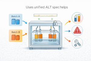
Same yardstick: compare batches and alternates under the same environment.
Quality up front: expose “early weaknesses” before shipment.
Actionable improvements: convert fails into clear process tweaks (loading/passes, edge weighting, zone control, inter-pass cooling).
Traceable documents: full test report + batch records so engineering and purchasing can decide together.
Online library: more templates and cases on our QC page 👉 https://ehisenelectrode.com/quality-control/
In the absence of a global standard, a unified, company-level ALT spec becomes our shared language. Ehisen can quickly align to your industry scenario and test every batch in a consistent, traceable environment.
We ran systematic tests in this window: H₂SO₄ = 1–300 g/L, 40–60 °C, J = 0.01–3 A/cm². Three takeaways you can use right away:
Acid concentration (1–300 g/L) barely changes ALT life.
60 °C gives clearly shorter life than 40 °C under the same setup.
Life drops as current density (J) goes up—a strong inverse relationship.
To make supplier and lot comparisons fair, we suggest fixing the ALT at H₂SO₄ 150 g/L, 60 °C, then choosing a current-density tier for the purpose of the test.

What we saw: Within 1–300 g/L, ALT life barely moves. Most scatter comes from part-to-part and process differences, not from acid level.
What to do:
Lock the spec at 150 g/L H₂SO₄ in your ALT agreement.
If you want a light/heavy cross-check, you can add a couple of samples at 50–80 g/L and 250–300 g/L, but keep the decision rule based on 150 g/L.
Note: If your real process has Cl⁻/F⁻ or organics, run a small check first—the “acid-insensitive” result can change.
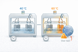
What we saw: With everything else fixed, 60 °C produces a shorter ALT life than 40 °C. Heat speeds reactions and reveals weak spots faster.
What to do:
Use 60 °C as the standard acceleration for screening and lot release.
Use 40 °C as a control when you need to diagnose mechanism shift.
Log heat–soak–cool curves; avoid “over-burn” (bluish tint, grain growth).
What we saw (at 150 g/L, 60 °C): Higher J → shorter life. More overpotential and heat expose edges/holes/welds first. Pulsed loads can be harsher than DC at the same average J—fix and record frequency/duty if you use pulses.
Suggested tiers (easy to agree in contracts):
| Tier | J (A/cm²) | Use case | Expected life |
|---|---|---|---|
| Mild (Screening) | 0.1–0.2 | Early recipe screening, quick sample compare | Long |
| Moderate (Qualification) | 0.5–1.0 | Small-lot release, supplier comparison | Medium |
| Severe (Stress) | 2.0–3.0 | Mechanism check, harsh boundary | Short |
Execution tips:
Fix gap, counter-electrode, area ratio, stirring/flow so mass-transfer differences don’t fake “life” differences.
For mesh/holed parts, define edge/hole weighting paths to reduce geometry bias.
Different coatings can use different noble-metal loadings (g/m²). To compare fairly, report a Standard Accelerated Life (SAL):
Plain meaning: Under the agreed ALT conditions, how many “ten-thousand hours” of accelerated operation you get per gram of Iridium on the surface.
How to read: We write it as SAL = X.X ten-thousand hours per g(Ir).
Example: SAL = 3.0 means about 3.0 × 10⁴ hours per gram of Ir under the same ALT window. Higher is better (more life per gram of Ir).
Important: SAL is only meaningful when conditions are the same: acid (150 g/L) + temperature (60 °C) + J (and pulse settings if used).
Mini example (apples-to-apples):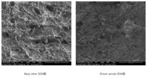
Supplier A: SAL = 3.6
Supplier B: SAL = 2.4
With the same ALT window, A uses Ir more efficiently (better per-gram life). If the windows differ, this comparison is invalid.
Mechanism shift (bluish/over-burn): lower T or J, shorten stress time; compare to a 40 °C control run.
Edge/hole fail first: add edge/hole weighting and fixture/path improvements.
Big lot-to-lot scatter: check inter-pass cooling, zoned temperature control, pass count, and geometry differences.
Non-comparable reports: align acid/temperature/J/pulse/geometry and always include SAL.
In 1–300 g/L acid, ALT life is driven mainly by temperature and current density.
Fix the ALT at H₂SO₄ 150 g/L, 60 °C; set J tiers by purpose.
Ask every report to include SAL (ten-thousand hours per g Ir) plus the exact conditions.
Use ≥ 3 pcs, show mean/SD, attach key curves and any exception analysis.
Using the same window + SAL puts all suppliers and batches on the same yardstick—clearer quality control and better cost decisions.
Why buyers care: A standardized ALT window gives every supplier the same yardstick. Results become comparable, controllable, and traceable—fewer disputes, faster approvals, and clearer links between price, noble-metal use, and life.

Lock these so different labs don’t “use their own recipe”:
Electrolyte: 1 mol/L H₂SO₄ (same composition & concentration).
Temperature: 40 °C (control/diagnosis) and 60 °C (acceleration/release).
Geometry & flow: Keep electrode gap, counter-electrode material & area ratio, stirring/flow constant and recorded.
If your real process has Cl⁻/F⁻ or organics, run a small check first, then extend this baseline as needed.
In our window, life is most sensitive to J. Standardize J so you can see who is truly more durable and more efficient with precious metal.
Chlorine evolution (CER) coatings: test at 1 A/cm² and 2 A/cm²; prefer 2 A/cm² (stronger acceleration).
Oxygen evolution (OER) coatings: test at 3 / 4 / 5 / 6 A/cm²; prefer 4 A/cm² (good balance of acceleration vs. mechanism stability).
Startup voltage gate (V₀):
Measure V₀ at the start of the test under the chosen J.
If V₀ ≤ 5 V, proceed at that J.
If V₀ > 5 V, lower J or optimize gap/flow first—avoid mechanism shift (over-burn / pure chemical attack).
Quick lookup
| System | Recommended J (A/cm²) | Preferred | Release note |
|---|---|---|---|
| CER | 1, 2 | 2 | Use 2 A/cm² if V₀ ≤ 5 V; if higher, drop to 1 A/cm² |
| OER | 3, 4, 5, 6 | 4 | Use 4 A/cm² for routine release; go 5–6 A/cm² only for boundary checks |
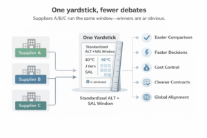
One yardstick, fewer debates: Suppliers A/B/C run the same window—winners are obvious.
Faster releases: 60 °C accelerates screening; 40 °C helps diagnose mechanism shifts (so you don’t reject a good recipe by mistake).
Cost control: Tie life to precious-metal efficiency (see SAL below), not just grams.
Cleaner contracts & warranty: Standard ALT + SAL lets you write clear quality/warranty clauses.
Global alignment: Multi-site testing reads the same when everyone follows the same template.
Plain meaning: Under the agreed ALT window, how many “ten-thousand hours” you get per gram of Iridium on the surface.
How we write it: SAL = X.X ten-thousand hours / g(Ir). Higher = more life per gram, better efficiency.
Why you need it: Different lots use different g/m². SAL removes the loading effect so you compare real coating quality, not just thickness.
Must include with SAL: electrolyte (1 mol/L H₂SO₄), temperature (40/60 °C), J (and pulse settings if any), gap, area ratio, and flow.
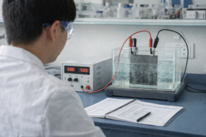
Electrolyte: 1 mol/L H₂SO₄. Temperature: 40 °C (control), 60 °C (acceleration).
Current density: CER = 2 A/cm², OER = 4 A/cm² (other tiers by written approval).
Startup gate: Begin only if V₀ ≤ 5 V at the chosen J; otherwise lower J or adjust gap/flow before testing.
End-of-life (EOL): ΔV beyond threshold (e.g., 50–100 mV) or visible flaking / black-wipe.
Statistics: ≥ 3 pcs per tier; report mean / SD and outlier rule.
Deliverables: voltage–time curve; temperature/pH/J traces; add polarization/EIS for exceptions; SEM/EDS, XRD, XPS, cross-section if failure analysis is needed.
Result format: Provide SAL (ten-thousand hours / g Ir) plus pass / caution / fail guidance.
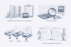
Multiple yardsticks in one project: Normalize to this scheme and re-state results as SAL.
Bluish tint / sudden resistance rise: likely over-burn—ask supplier to reduce T or J and rerun; include curves/photos.
Edges/holes/welds failing first: require edge/hole weighting paths & fixtures in the report.
Big lot scatter: ask for per-pass drying/sintering logs, inter-pass cooling records, zone control settings.
Non-comparable reports: return for re-test and re-report using the same template + SAL.
Standardize ALT to 1 mol/L H₂SO₄ + 40/60 °C + (CER 2 A/cm², OER 4 A/cm², with V₀ ≤ 5 V), and judge results with SAL. This puts all suppliers and lots on the same line—so you see who lasts longer, who uses Ir better, and who is more stable, at a glance.
This section has two parts: A) what we need from you to set clear test standards, and B) what Ehisen will propose and execute once you approve.
Usage conditions (most important)
Current load: DC or pulsed (frequency & duty).
Electrolyte: components (any Cl⁻/F⁻/organics), pH, temperature range.
Operating rhythm: continuous or intermittent; typical run time per cycle.
Startup cell voltage limit you care about (e.g., ≤ 5 V).
Life target & end-of-life (EOL) rule
Target as calendar time, Ah·m⁻², or accelerated hours.
EOL definition: ΔV threshold (e.g., 50–100 mV) and/or black-wipe / visible flaking.
Part geometry & fixturing
Plate/mesh/tube/wire, hole edge distances, bends, weld zones, blind zones.
Electrode gap, counter-electrode, area ratio, flow/stirring limits.
Whether you want edge/hole thickening or shielding.
Quality–cost preference
Prioritize long life, lower precious-metal usage, or a balanced plan.
Allowed loading tolerance and pricing/lock rules for precious metals.
Alignment & reporting
OK to use unified ALT window? (recommended: 1 mol/L H₂SO₄; 40/60 °C; J by CER/OER).
Report format: accept SAL (“ten-thousand hours per gram Ir”) as the common index?
Any third-party or on-site verification needed?
We can send you a one-page “Operating Conditions & Test Alignment” form so you can fill this in quickly.
Stage 0 — Align: Lock the ALT window (1 mol/L H₂SO₄; 40/60 °C) and J tiers (CER: 1/2 A·cm²; OER: 3/4/5/6 A·cm²; defaults: 2 for CER, 4 for OER).
Stage 1 — Incoming & in-process: Size/GD&T, weld look (color should be silver–light straw), scratches/cracks/scale; PT if needed.
Stage 2 — Coating surface & loading: Visual, pinholes/runs, XRF loading & uniformity (heatmap), four-point resistance; confirm edge/hole/bend weighting.
Stage 3 — ALT (accelerated life): Run light / medium / heavy tiers (≥ 3 pcs each); provide voltage–time curves and summary stats.
Stage 4 — Lab analysis (optional): For any abnormal sample, do SEM/EDS, XRD, XPS, cross-section to locate the root cause and suggest tweaks.
Stage 5 — Release & traceability: Deliver COA + batch records (per-pass dry/sinter/cool, TC map), and the SAL index with pass / caution / fail guidance.
| Your focus | What we test/record | How we decide |
|---|---|---|
| Will it meet life? | Unified ALT window + voltage–time curve | SAL (ten-thousand hours per g Ir) + ΔV rule |
| Precious-metal efficiency | XRF loading (g/m²) + ALT charge | Higher SAL = more life per gram |
| Edges/holes failing? | Edge/hole weighting plan + XRF heatmap + photos | Edge/hole pass rate, local ΔV |
| Weld impact | Weld color/shape, PT, repair log | Must be silver–light straw; no black-wipe |
| Lot consistency | Per-pass dry/sinter/cool logs; zone control | Variability band + any outliers explained |
Electrolyte & temp: 1 mol/L H₂SO₄; 40 °C (control) and 60 °C (acceleration).
Current density (J): CER = 2 A/cm² (optionally 1); OER = 4 A/cm² (5–6 for boundary checks).
Startup gate: begin only if V₀ ≤ 5 V at the chosen J; otherwise lower J or adjust gap/flow.
Statistics: ≥ 3 pcs per tier; report mean/SD and outlier rule.
EOL: ΔV over threshold (e.g., 50–100 mV) or black-wipe / visible flaking.
Result format: always provide SAL and list all conditions (electrolyte, temp, J/pulse, gap, area ratio, flow).
Need ready-to-use templates? We can share ALT agreement and report templates so your plants or third-party labs can run the same playbook.
Below is the standard report set we can provide at incoming, in-process, coating, and life-test stages. Our files follow ISO 9001 controls (unique IDs, revision history, sign-off, calibration traceability, and archiving against your contract/PO and lot number).
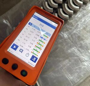
Spectrometer report (optical/handheld as appropriate): full chemical composition table, device model, calibration validity, and QC photos.
Mill Test Certificate (MTC) from the supplier, linked to our lot ID.
Third-party spot checks (ISO/IEC 17025 lab) by batch when required, with a formal report (often includes EDS spectra and SEM photos if needed).
Traceability: lot/heat/PO numbers tied to all documents and labels.
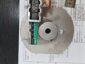
We measure 2–3 points per dimension (more for critical features).
CMM 3D report (PDF/CSV) with nominal / actual / deviation, stats, probe map/snapshots, instrument ID & calibration date, operator + reviewer sign-off.
Simple tools (calipers, projector/vision) are listed as supporting devices with ID & due-date for calibration.
All reports carry a unique document number and are archived under your contract.
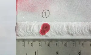
Low-angle light photos for scratches, cracks, scale, burrs.
Weld photos and color check (silver → light straw = OK; blue/purple/black = reject/repair); PT (dye-penetrant) report if used.
Repair records (before/after photos, parameters, and re-inspection results).
XRF loading/thickness report with uniformity heatmap (edges/holes/bends highlighted).
Cross-section thickness (optical/SEM) with scale bars and layer labels.
Precious-metal mass control: before/after weight photos and short video, plus balance ID & calibration info.
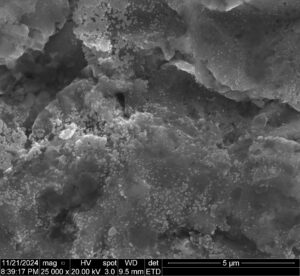
Optional SEM/EDS (surface & cross-section), XRD (phase), XPS (surface chemistry). Each includes test conditions and raw-data references for review.
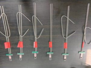
Bend test (e.g., 180° without visible flaking): photos/video + pass/fail notes.
Tape / cross-hatch test with method level and pictures.
Surface roughness (Ra) readings with location sketch.
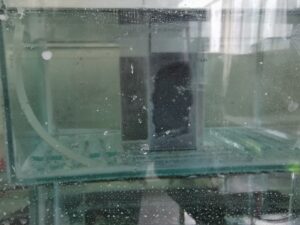
ALT data pack: electrolyte/temperature/J/geometry/flow settings, voltage–time curves, and statistics (mean/SD/outlier rule).
SAL index—our standard, buyer-friendly metric (“ten-thousand hours per gram of Ir”), plus Pass / Caution / Fail guidance.
For exceptions, we can add polarization/EIS and failure-spot SEM/EDS/XRD/XPS/cross-section.
Every file has a unique ID, revision/version, and approval trail (prepared → reviewed → approved).
Calibration traceability for all instruments (CMM, spectrometer, XRF, balances, etc.).
Retention & retrieval: electronic + paper, stored under your contract/lot; fast search by ID or date.
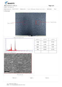
COA/CoC (certificate of analysis/conformity)
Incoming chemistry (spectrometer + MTC + optional 3rd-party report)
Dimensions & GD&T (CMM + vision snapshots + tool list)
Surface & weld (photos, PT if used, repair close-out)
Coating (XRF loading/thickness + heatmap, cross-section, optional 4-point resistance)
Adhesion/mechanics (bend, tape/cross-hatch)
Precious-metal mass chain (pre/post weights, photos/video, records)
ALT life (conditions, curves, stats, SAL index, conclusion)
Third-party accredited reports (on request)
Traceability list (batch IDs, per-pass dry/sinter/cool times, furnace/TC map, operator, fixtures)
If you require extra items (e.g., salt-spray, spark test threshold, specific electrolyte simulations), we can arrange accredited third-party labs and include their official certificates/reports. Bilingual (EN/CN) or your template formats are available.
Bottom line: You get a clean, ISO-style document trail—numbered, signed, traceable, and easy to audit—plus the key metrics (CMM, XRF, ALT, SAL) that support technical reviews and pricing decisions.
What “traceable” means for you: every number on the COA can be walked back to who/what/when/where/how, and walked forward to which parts were shipped. That chain is reproducible and auditable on request.
Lot genealogy: PO → Heat/Lot → Sub-lot → Piece → Sample → Test ID. Each step has its own ID and time stamp.
Test-window tag: every test carries a compact tag with the electrolyte, temperature, current mode (J / pulse), gap, area ratio, flow and the method version. That lets different labs compare apples-to-apples.
Device provenance: reports embed instrument ID, calibration due date, and operator/reviewer codes. If a method is updated, the method version increments and is logged.
Raw data retained: we keep the native files behind the PDF (e.g., CMM point clouds, XRF spectra, voltage–time CSVs) plus photo/video evidence of critical steps.
Witness coupons: for coating/life tests we reserve reference coupons per lot, so re-checks don’t consume shipped parts.
Change control & NCR/CAPA: any deviation, rework, or re-test is linked to the same lot via NCR/CAPA tickets, with cause, action, and closure proof.
Trace-back report: start from a COA/SAL number and see the exact ALT run, sample IDs, test-window tag, and the linked XRF/CMM files.
Trace-forward list: from a heat/lot, see which POs/boxes contain parts made from it.
Chain-of-custody pack (for audits): read-only PDFs + raw files index, instrument calibration proofs, method version history, and sign-off trail.
QR label option: shipping labels can include a QR code that opens the lot’s document index for quick checks on your side.
| Stage | Key linkers (examples) | Why it matters |
|---|---|---|
| Incoming material | Lot ID, heat number, MTC No., spectrometer file ID | Confirms chemistry → product family fit |
| Cutting/welding/machining | Router No., fixture ID, operator code, in-process photo set | Ties geometry & weld quality to later coating life |
| Coating/sintering | Pass count, furnace/zone ID, TC map, inter-pass cooling log | Explains adhesion/phase differences if any |
| Coating QA | XRF job ID, uniformity heatmap ID, cross-section image ID | Shows loading and thickness that drive life |
| ALT (life) | ALT run ID, test-window tag, voltage–time CSV ID | Source behind SAL on the COA |
| Exceptions | NCR/CAPA ID, rework ticket, retest ID | Ensures issues were closed properly |
Reproduce: pull the witness coupon and re-run under the same test-window tag.
Corroborate: share raw files (CMM/XRF/ALT CSV) and, if needed, send a coupon to an accredited third party for an independent check.
Close the loop: if a gap is found, we issue CAPA, update the method version, and annotate the affected lots—so the lesson is permanent.
Read-only PDFs for day-to-day; raw files available for audits or joint investigations.
All documents carry unique IDs, revision history, and signatures; instruments are calibration-tracked.
Customer drawings/data are handled under NDA; only the minimum necessary info is shared externally.
Bottom line: Your results aren’t just numbers on a page—they’re tied to a full, navigable history. That’s how we make quality verifiable, comparisons fair, and decisions fast.
At Ehisen, we believe reliable titanium anodes start with reliable quality control. Precision, discipline, and transparency are the backbone of our inspection program—from incoming materials to final accelerated life testing (ALT). We’re not just a supplier; we’re your quality partner, aligning methods and metrics so results are trusted on both sides.
We work with you to define a clear, unified test window and reporting format before production begins. That means locking the basics (e.g., 1 mol/L H₂SO₄; 40/60 °C; current density by CER/OER) and agreeing on how success is measured (e.g., ΔV thresholds and SAL—“ten-thousand hours per gram Ir”). Whether you need tighter edge/hole coverage checks, weld verification, or specific third-party audits, we tailor the plan to your performance and cost targets.
Quality for us is end-to-end: spectrometer chemistry + MTC at incoming, CMM dimensional reports in process, XRF loading/heatmaps and cross-sections after coating, and ALT data packs with full curves and statistics. Every file carries a unique ID, calibration traceability, and sign-off, and every lot can be traced forward and back—so questions get answers, fast.
We see every nonconformance as a chance to improve. With root-cause tools (SEM/EDS, XRD, XPS) and a disciplined CAPA loop, we turn findings into stable process controls—things like zoned furnace settings, inter-pass cooling logs, and edge-weighting routes. From the first alignment call to shipment and after-sales support, our promise is simple: clear data, comparable tests, and
Finding a reliable processor of titanium products is essential to your business success, and Ehisen is here to be that partner.
Send us a message if you have any questions or request a quote. We will be back to you ASAP!