Precision Sintering & Multi-Coating for Superior Performance
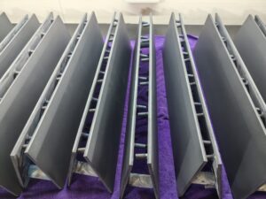
At Ehisen, we apply a controlled coat–sinter–recoat process to titanium anodes using precisely formulated precious-metal solutions. You share target noble-metal loading or operating parameters (current density, electrolyte, temperature, pulse/reverse-pulse), and our engineers define the bath chemistry, number of coats, and sintering profile. Layer-by-layer sintering creates a dense, uniform, strongly bonded oxide layer that lowers resistance, stabilizes current distribution, and extends service life—cutting downtime and total cost. We offer Iridium-Tantalum, Ruthenium-Iridium, Platinum-Coated, and MMO systems with traceable QA (COA, life testing, and optional third-party reports) to keep film thickness and loading consistent across batches. Proven in hydrogen production, electroplating, water treatment, and cathodic protection, this process helps projects pass trials faster and scale smoothly. We work closely with your team to match coating recipes to real operating conditions, delivering cost-effective and reliable electrochemical performance.
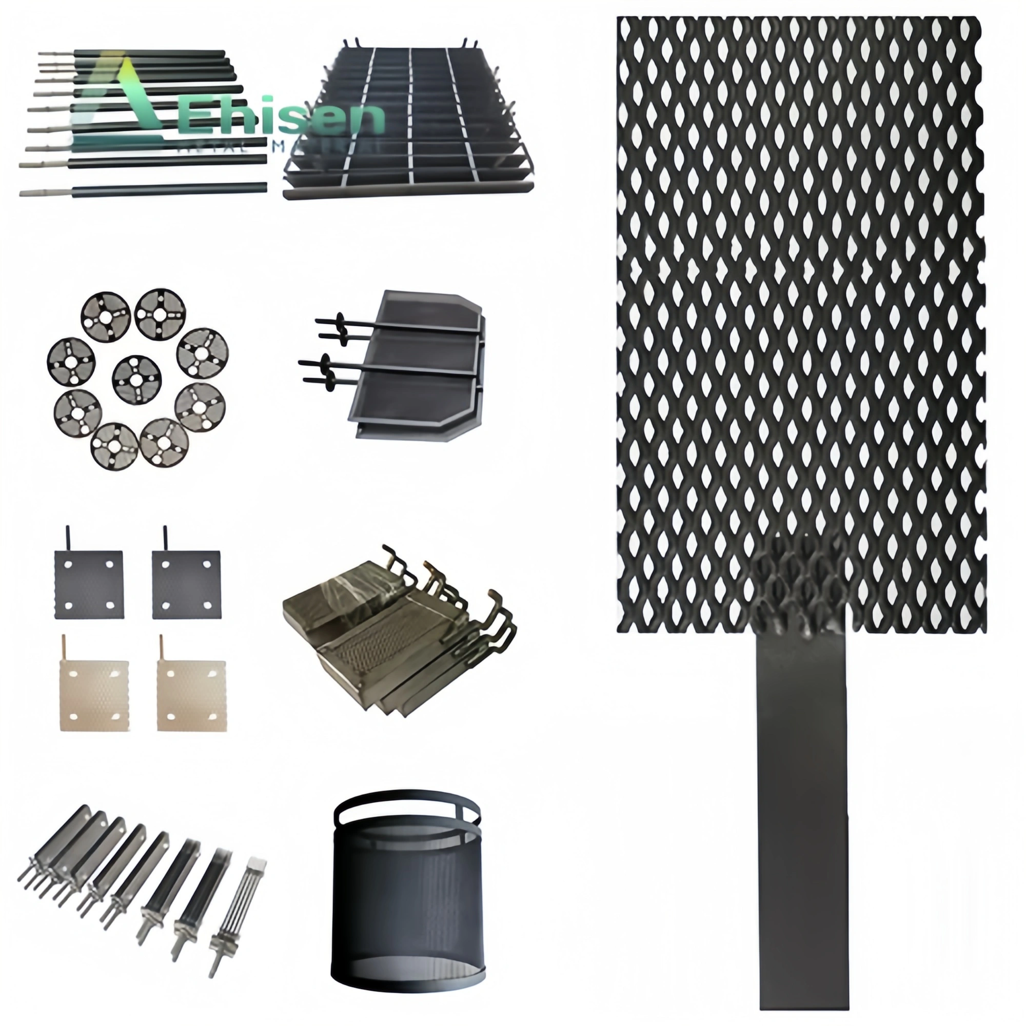
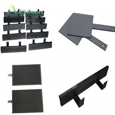
MMO Titanium Anode
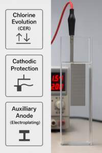
MMO (Mixed Metal Oxide) titanium anodes deliver strong corrosion resistance and high catalytic activity, excelling in chlorine evolution reactions (CER) and supporting OER where needed. Built for high current densities and saline/acidic environments, they are widely used in electrochlorination, wastewater treatment, electroplating lines, and impressed-current cathodic protection. Optimized MMO coatings extend service life, maintain stable voltage, and reduce energy and maintenance costs—ensuring reliable, consistent performance for demanding industrial operations.
Dimensionally Stable Anode (DSA)
Dimensionally stable anodes keep their shape and performance over long runs, delivering low voltage drift and uniform current distribution. They are ideal for electrochlorination, cathodic protection, electroplating, and wastewater treatment, performing well under high current density and corrosive media. With corrosion-resistant MMO coatings on titanium, DSAs reduce maintenance and downtime; tailored coating formulations match your lifetime and energy targets, ensuring reliable, cost-effective operation in demanding industrial environments.
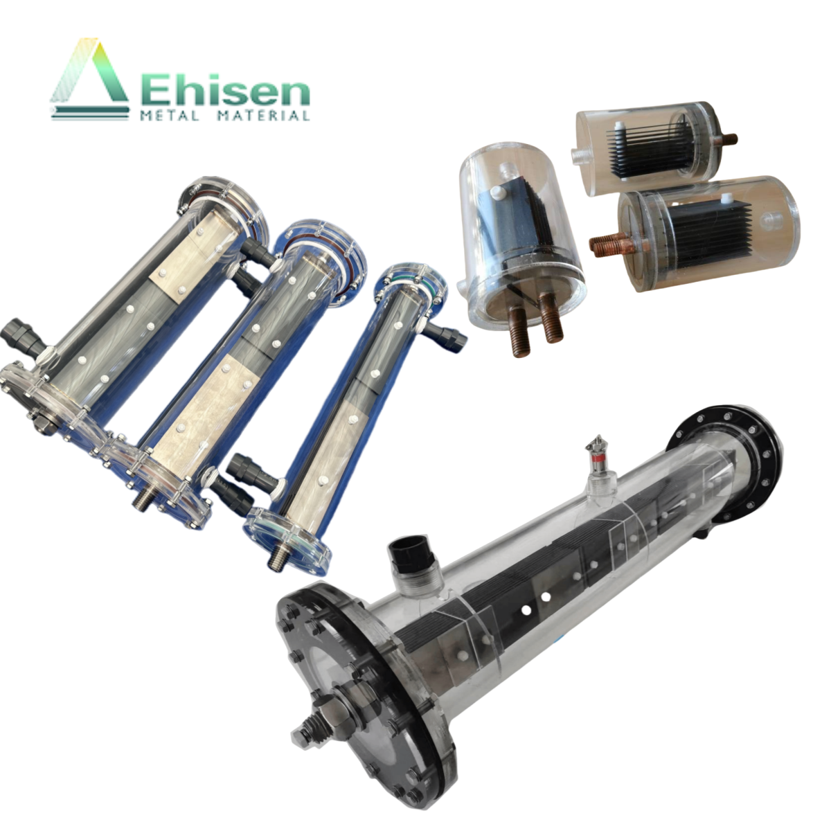
Sodium Hypochlorite Generator
Sodium hypochlorite generators make NaOCl on site from salt and water using Ru–Ir coated titanium anodes. Built for continuous electrochlorination in municipal water, seawater intakes, cooling towers, and wastewater, they lower chemical storage risks and logistics costs. Standard outputs: 30g/h, 50 g/h, 100 g/h, 200 g/h, 500 g/h, 1000 g/h, 2000g/h (custom options available). The Ru–Ir coating delivers high current efficiency, stable concentration, long service life, and low maintenance.
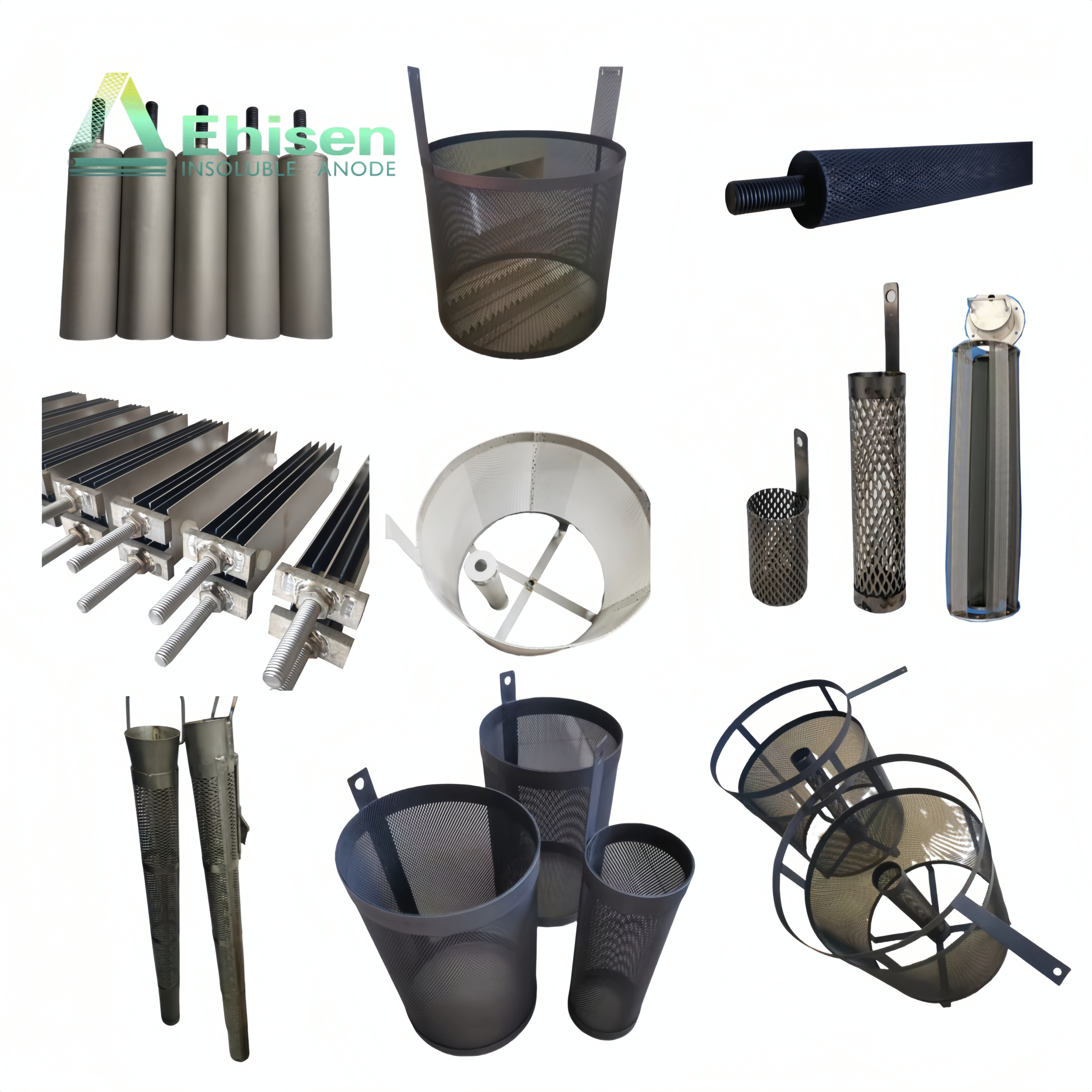
titanium anode baskets
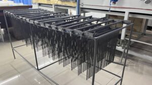
Titanium anode baskets are durable, corrosion-resistant carriers for metal chips and pellets in plating tanks. With MMO or platinum coatings, they resist acids/chlorides, keep stable voltage, and deliver uniform current. Round/rectangular mesh with reinforced rims and hooks improves solution flow and loading. Baskets reduce sludge, prevent passivation, and improve thickness uniformity—cutting downtime and maintenance. Custom sizes and mesh match different chemistries and current densities for cost-effective production.
Electroplating & Pyrolysis Process Schematic
About Us
Why Choose Ehisen for Brush Coating & Sintering on Titanium Anodes?
At Ehisen, we tailor brush coating and staged sintering of precious-metal layers on titanium anodes to your operating conditions—boosting lifetime, efficiency, and batch consistency. Here’s how our approach adds value to your projects:
R&D Focus on Brush Coating and Sintering
Our production lead has 15 years of titanium anode experience and oversees every order. We focus on precious-metal brush coating with staged sintering. With small/medium/large furnaces and segmented temperature control, we keep even heat, dense sintering, and strong repeatability—meeting your specs at the lowest practical production cost.
Parameter-Driven Formulation
You provide current density, electrolyte/medium, temperature, duty cycle/pulse mode, and target noble-metal loading. We then prepare the solution; the loading defines coat count and the sintering profile. Even with the same metal loading, different processes and brushing methods can change lifetime—we pick the best route for your conditions.
Strong Adhesion, Low Resistance, Multi-Layer Design
Repeated “coat–sinter–recoat” builds a dense, graded active layer with high bond strength and low drop-off risk. The result is low resistance, stable potential, longer service life, and lower energy and downtime—ideal for long, continuous operation.
Dr. Miao
Technical Director of Ehisen
Spencer Xu
CEO of Ehisen
Consistency and Traceable QA
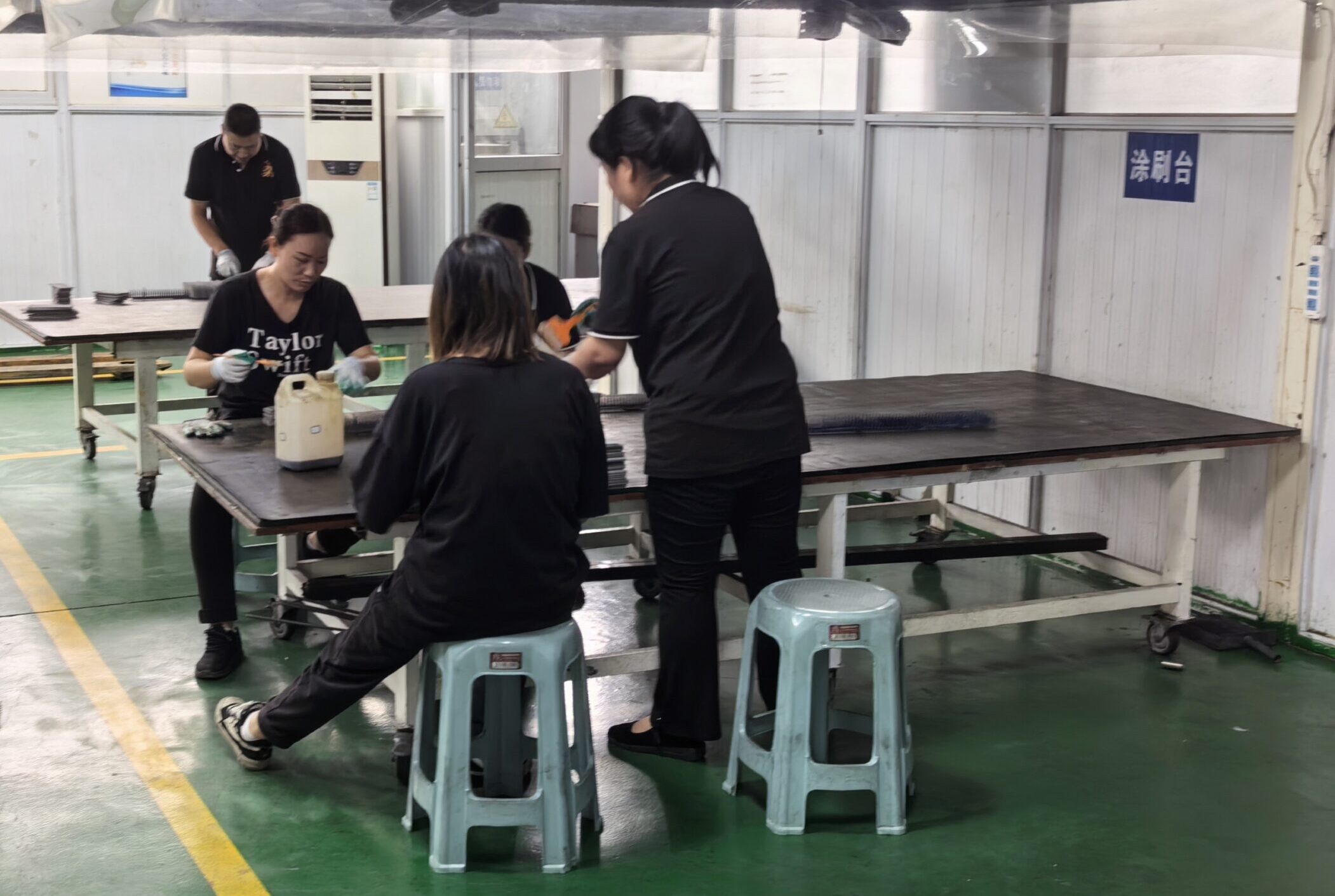
All brush workers are full-time employees, giving stable workmanship and process consistency. We control per-layer weight gain, thickness, and furnace temperature curves. The plant follows ISO9001 and ISO14001, with COA, life testing, and optional third-party reports—so issues can be traced fast and your procurement risk is lower.
Scalable Lines and On-Time Delivery
Multiple automated lines plus the “Titanium Valley” supply chain mean full substrate options and controlled lead times. Segmented-control furnaces support quick changeover from samples to pilot runs to mass production, keeping validation and ramp-up smooth.
End-to-End Support and Metal Recovery
Our engineers communicate in English and provide on-site/remote process guidance and failure analysis. We also offer precious-metal recovery and re-coating. Based on cost and lifetime targets, we design the most cost-effective supply plan to deliver the best value.
Why Understanding Brush Coating & Sintering Steps Matters for Procurement Professionals
For buyers of titanium anodes, knowing the brush-coating and sintering workflow is critical. Each step—surface preparation, solution formulation, brush application, staged sintering, and per-layer inspection—directly affects adhesion, voltage stability, and service life. At Ehisen, we map these steps to your operating data (current density, electrolyte, temperature, duty cycle) and target precious-metal loading, then define coat count and furnace profile to meet your lifetime and energy goals. This process transparency helps you read quotes correctly: you can see how coating weight (g/m²), number of passes, sintering holds, and QA (ISO9001 records, COA, life tests) drive cost and performance. Whether the chemistry is Ru–Ir, Ir–Ta, or Pt, understanding the step-by-step build gives you confidence that pricing is fair, specifications fit your application, and batches will be traceable and consistent—reducing total cost of ownership and avoiding mismatches in field performance.
Table of Contents
Chapter 1:Coating Application & Film Uniformity
Why do titanium anodes follow a “coat–dry–thermal oxidize–cool–repeat” cadence?
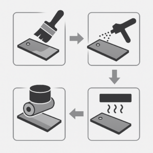
When evaluating titanium anode coating processes, it’s essential to understand the end-to-end sequence and what each stage achieves. For MMO (Ru/Ir/Ta) oxide systems, the manufacturing cadence is:
Surface Pretreatment → Coating (brush/spray/roll) → 100–200 °C complete drying → ≥ 400 °C thermal oxidation (typ. 10–15 min) → forced cooling to room temp → repeat multi-pass.
Below is a concise overview of each step and its role in building a durable, conductive, and catalytically active coating.
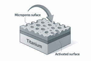
1) Surface Pretreatment (Foundation for adhesion)
Purpose: Degrease, activate, and micro-roughen the Ti substrate to ensure wetting and mechanical interlock.
Outcome: Clean, chemically active surface that enables strong coating–substrate bonding and uniform wet-film laydown.
Applies to: All subsequent coating methods (brush, electrostatic spray, roll).
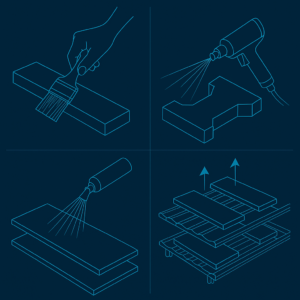
2) Coating Application (Brush / Electrostatic Spray / Roll)
Goal: Deposit a uniform wet film of noble-metal precursors.
Brush coating: Most common; precise local control and edge coverage.
Electrostatic spray: Efficient for complex geometries and large areas.
Roll coating: Suited to flat parts and takt-time production.
Key deliverable: Even wet film with controlled thickness and minimal runs/holidays, ready for solvent removal.
3) Drying at 100–200 °C (Complete solvent removal)
Purpose: Use far-infrared (preferred) and/or hot air to fully evaporate solvents before high-temperature conversion.
Typical Window: 100–200 °C until mass/appearance stabilizes; hot-air assist as needed.
Why it matters: Any residual solvent carried into oxidation can create porosity defects, reduce adhesion, and impair electrochemical consistency.
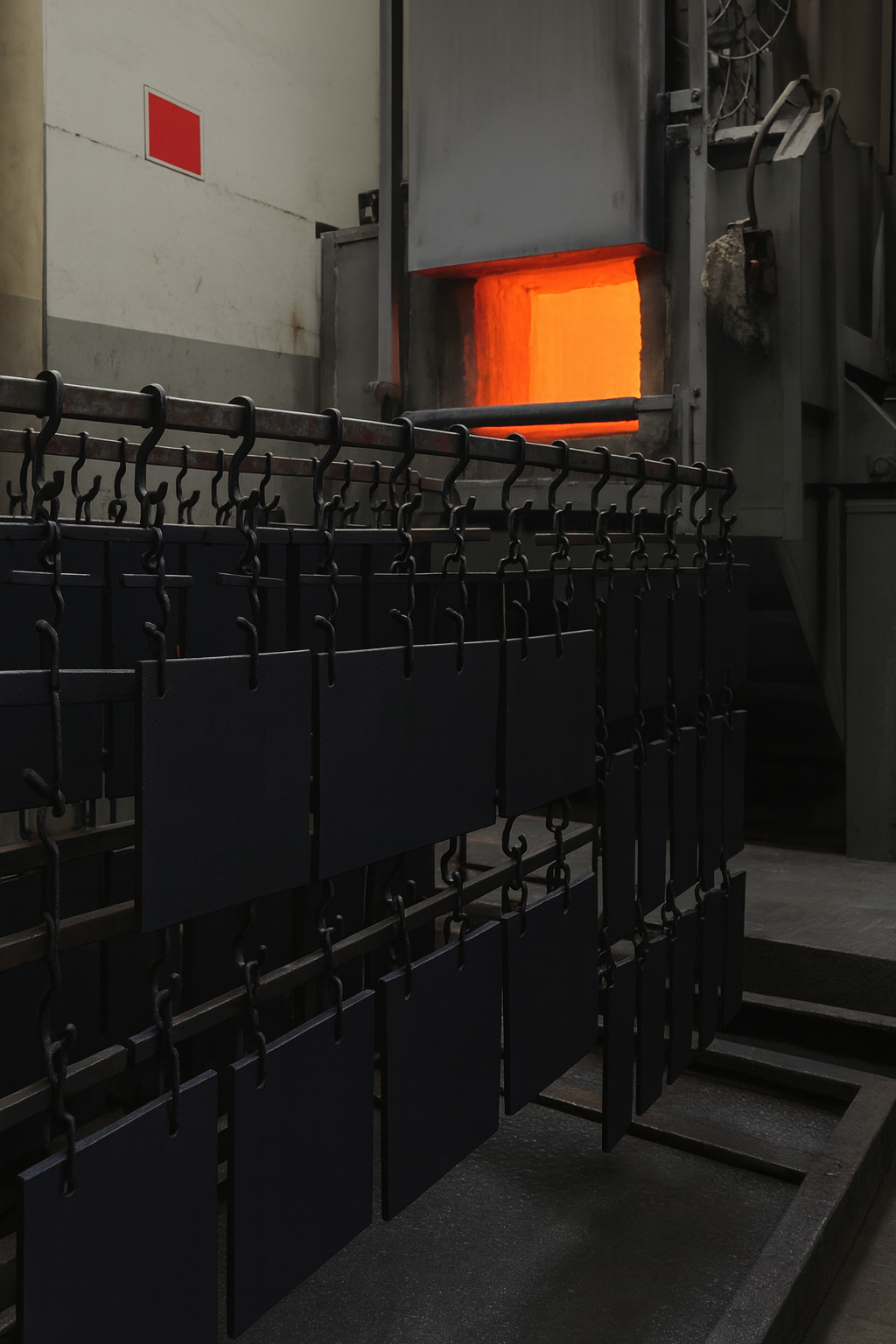
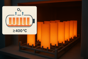
4) Thermal Oxidation ≥ 400 °C, 10–15 min (Phase formation & conductivity)
Objective: Thermally convert metal salts to conductive, catalytically active oxides in an oxidizing atmosphere (required for RuO₂-based systems).
Typical Window: ≥ 400 °C, 10–15 min dwell per pass.
Phase Target: Rutile-type RuO₂/TiO₂ solid solution, delivering low resistivity and stable catalytic activity.
Temperature sensitivity:
Too high: Excess dechlorination and grain coarsening → higher resistivity, lower adhesion.
Too low: Incomplete oxidation → weaker adhesion, under-developed catalytic phase.
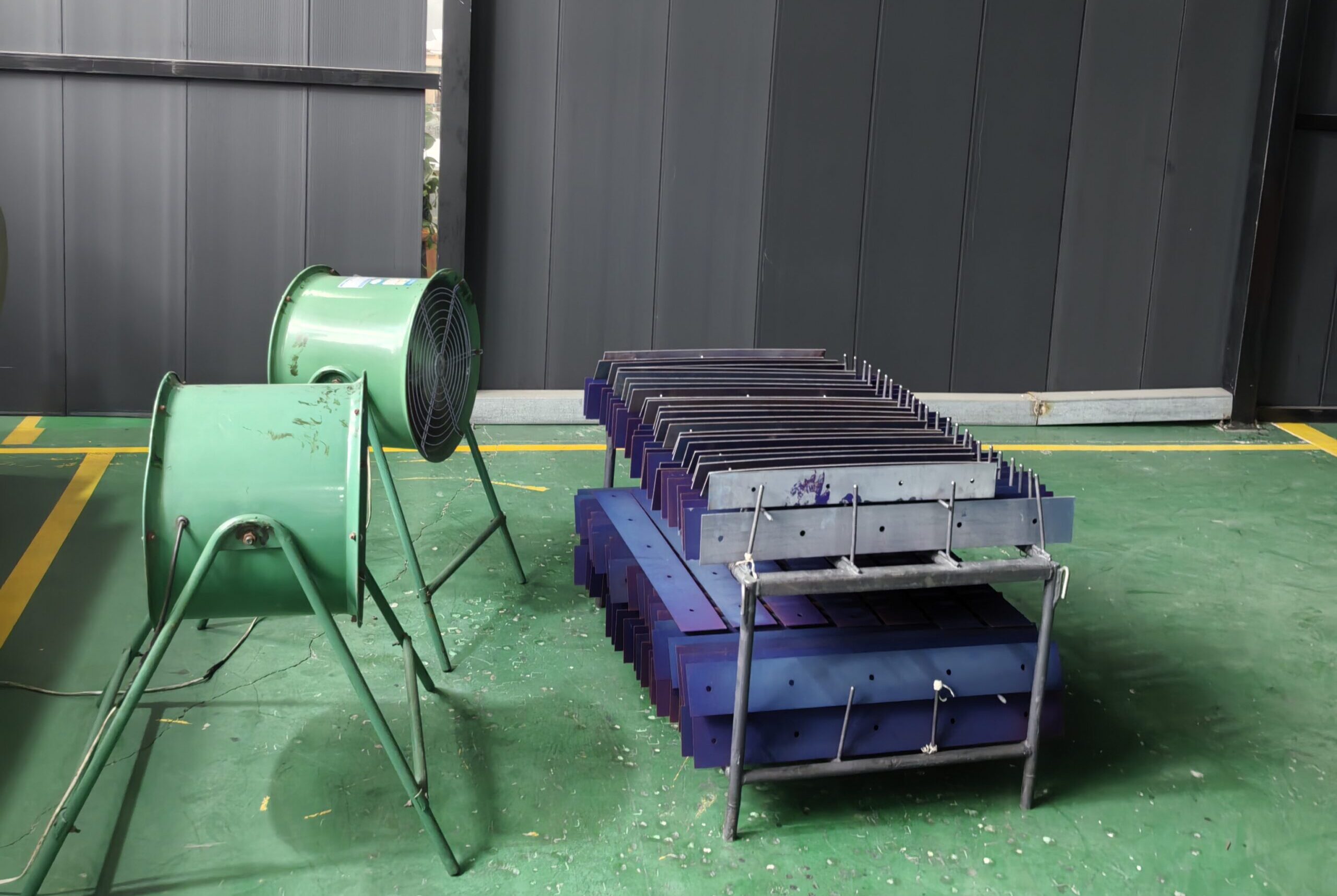
5) Forced Cooling to Room Temperature (Cycle reset)
Requirement: After each oxidation pass, force-cool to room temperature before the next coating.
Outcome: Stabilizes the layer, resets diffusion conditions, and preserves uniformity in subsequent passes.
6) Multi-Pass Build-Up (From porous to compact)
Method: Repeat Coat → Dry → Oxidize → Cool to build the functional stack.
Microstructure evolution: Early layers are relatively porous; with increasing passes, porosity decreases and the coating densifies, improving adhesion, conductivity, and lifetime.
Applies to: Ru/Ir/Ta MMO oxides and other platinum-group oxide coatings requiring oxidizing atmospheres.
Summary (What this sequence ensures)
A repeatable, multi-pass route that couples full drying, controlled oxidation, and complete cool-down.
Formation of the intended rutile-rich oxide phase with balanced conductivity, adhesion, and catalytic activity.
A stable platform for the next sections: 1.2 (operation cautions) and 1.3 (issue → fix → impact), which will expand on best-practice controls and troubleshooting.
How do you ensure uniformity and adhesion in each coating pass?
Scope: Multi-pass coating process for MMO (Ru/Ir/Ta) titanium anodes
Objective: High adhesion, low resistivity, and stable catalytic phases with consistency and repeatability
A. Coating (Brush / Electrostatic Spray / Roll)
Substrate condition: After oxidation, force-cool to room temperature before the next coat. Do not coat on warm parts (risk of skinning/solvent entrapment).
Environment & cleanliness: Clean, dust-controlled, moderate ventilation; fixtures must not contaminate the dope.
Coating control: Follow SOP viscosity and per-pass wet-film limit; prevent runs/holidays; secure edge and hole coverage.
Method selection:
Brush: precise local/edge control;
Electrostatic spray: complex shapes & large areas;
Roll: flat parts and takt-time production.
Placement & cadence: Hanging/laying orientation to avoid pooling/overlap marks; log pass number and area.
B. Drying (100–200 °C, far-infrared preferred)
Complete solvent removal: Use far-IR as primary, hot-air assist if needed; confirm mass/appearance stability, no solvent odor, no tack as “fully dry” criteria.
Temperature & time: Run within 100–200 °C and never shortcut; residual solvent carried into oxidation causes voids, poorer adhesion, and electrochemical drift.
Uniformity: Stable airflow without dust; adequate spacing to avoid “shadow” under-drying.
C. Thermal Oxidation (≥400 °C, typ. 10–15 min, oxidizing atmosphere)
Atmosphere: RuO₂-type PGM oxides require oxidizing conditions (air/O₂). Reducing atmospheres are unsuitable.
Temperature window: Choose ≥400 °C per recipe; too high → over-dechlorination & grain coarsening → higher resistivity / weaker adhesion; too low → incomplete oxidation → under-developed catalytic phase / weak adhesion.
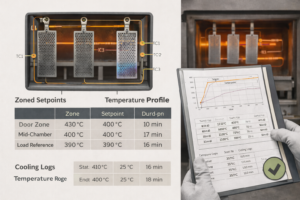
Zoned control: Compensate door-zone cooling during loading by setting a higher local zone; log thermocouple positions and temperature profiles.
Loading rules: Maintain part spacing, avoid stacking/shadows; moderate ramps to minimize thermal-stress cracking.
Dwell cadence: Observe 10–15 min per pass; after each pass, force-cool to room temperature before recoating.
D. Inter-pass & general controls
Multi-pass build: Strict Coat → Dry → Oxidize → Cool cadence; porosity should decrease pass-by-pass, forming a dense functional stack.
No step skipping: Any deficiency (especially drying or cooling) will amplify in later passes.
Process records: For every pass, log method, wet-film limit, dryness criteria, zoned temperature profile, TC locations, forced-cooling time.
E. Quick shop-floor checks (fixes deferred to 1.3)
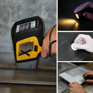
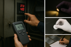
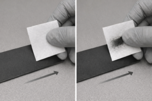
Filter-paper wipe: No visible black → good bonding; visible black → delamination risk (typical causes: low oxidation temp, excessive per-pass film, recoating without full cool-down).
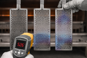
Color tone: Overall bluish tint may indicate over-temperature; re-check setpoints and zone compensation.
Low-angle light: Inspect pinholes/runs/overlaps; consider spot electrical resistance/continuity checks as needed.
Summary
The make-or-break controls are full drying and full cool-down, plus the right oxidation window & atmosphere.
Zoned temperature control + instrumented TCs ensure each pass truly meets setpoint & dwell.
Use rapid checks to police consistency; corrective actions and their impact on performance/cost/lead time will follow in 1.3.
How should peeling or bluish tint in titanium anode coatings be troubleshot and corrected?
Scope: Multi-pass MMO (Ru/Ir/Ta) titanium anode process
How to use: For each symptom, follow Cause → Immediate Fix → Long-term Prevention, then assess Performance/Cost/Lead-time impact.
A. Typical Issues & Remedies (Shop-Floor Ready)
Symptom / Quick Check | Likely Cause | Immediate Fix (this lot) | Long-term Prevention | Performance Impact | Cost / Lead-time Impact |
---|---|---|---|---|---|
Filter-paper shows visible black (peel-off) | Low oxidation temp; over-thick pass; recoated while warm; solvent carryover | Minor: rework (clean→light sand→thin recoat), re-oxidize within window; Major: scrap | Enforce per-pass wet-film limit; stronger dryness criteria; full cool-down before recoating | Poor adhesion & lifetime; electrochemical inconsistency | Extra furnace cycles & labor; scrap loss; schedule slip |
Overall bluish tint | Over-temperature/over-bake; excessive zone compensation; over dwell | Lower setpoint; remake last 1–2 thin passes and re-oxidize; local polish + re-bake if needed | Tight zoned control; periodic furnace mapping & TC calibration | Higher resistivity, weaker adhesion, lifetime scatter | Added rework & inspection; possible delay |
High/variable resistance | Over-dechlorination, grain coarsening; non-uniform thickness; under-drying | Restore recipe window; add uniform thin pass; add hot-air assist for drying | In-line spot/4-point resistance checks; viscosity/laydown control; fixture spacing | Worse conductivity, higher energy use, hot spots risk | Rework & re-test; delivery push |
Pinholes/runs/overlaps (seen under low-angle light) | Viscosity drift; dust; vertical pooling; over-thick pass | Local light sand → thin spot recoat → re-bake; improve ventilation/cleanliness | Standardize orientation & takt; spacing; cleanroom discipline | Pitting / early failure points | Minor = same day fix; multiple = +1 furnace cycle |
Whitish/under-formed spots | Under-oxidation; solvent residual; wrong atmosphere | Extend dwell / raise setpoint within recipe; strengthen drying | Oxidizing atmosphere only; solid dryness endpoint | Undeveloped catalytic phase; low initial activity | Extra dwell or pass; mild delay |
Edge/holes thin or thick | Poor edge control; unstable spray angle/speed | Targeted thin edge pass and re-bake | Edge playbook (chamfer, slow second brush); spray fixture QA | Edge corrosion / early failure | Local rework manageable; large area needs recoat |
Short lifetime | Wrong temp window; insufficient passes; weak pretreatment; contamination | Add 1–2 thin passes + compliant re-oxidation; rework to base if needed | Tighten pretreatment checks; align recipe/passes with duty | Lower durability/stability | Extra material & cycles; schedule slip |
Lot-to-lot variability | Poor zoned control; bad TC placement; dope/viscosity drift | Re-validate zone compensation & TC locations; re-verify mix | Lock temp profiles & mix logs; SPC on key CTQs | Inconsistent field performance | Higher process-control cost; takt instability |
Rework vs Scrap: If peel-off area or resistance out-of-spec exceeds your internal threshold (e.g., >20% over limit), prefer scrap to avoid cascading delays. Use your QMS limits.
B. Verification & Correction Flow (SOP)
Triage with filter-paper / low-angle light / spot resistance.
Pull records: wet film, dryness criteria, zoned profile, TC map, cool-down time.
Trial on coupons to validate revised setpoints.
Apply minimal fix: thin-pass + compliant re-bake; escalate to base-metal rework if required.
Re-qualify: appearance, resistance, wipe/adhesion; perform electrochemical sampling on critical lots.
Institutionalize learnings: update workcards & control charts (viscosity, laydown, zone compensation).
C. Quantified Guidance (Estimates)
Performance: Over-temp/over-thick can raise resistance by ~10–30%; under-oxidation can reduce initial activity by ~10–25% vs. baseline.
Cost: Typical rework adds 1–3 furnace cycles plus labor; base-metal rework incurs additional material & pretreatment.
Lead-time: Minor fixes +0.5–1 day; moderate rework +1–3 days; scrap & remake depends on line capacity.
D. Preventive Checklist (Daily Discipline)
Enforce per-pass wet film and viscosity windows.
Complete drying at 100–200 °C (far-IR + hot-air assist).
Oxidize at ≥400 °C, 10–15 min/pass, oxidizing atmosphere.
Force-cool to room temp before next coat.
Zoned control + TC logging with periodic furnace mapping.
Routine quick checks (filter-paper / low-angle light / spot resistance).
Summary
Stabilize the process where defects originate: wet film, drying, temperature window, cool-down, and zoned control.
When deviations occur, favor the thin-pass + compliant re-bake minimal path; if beyond limits, scrap early to protect the schedule. Make control visible and logged to keep performance, cost, and lead-time in balance.
Chapter 2:Buyer Operating Window, QC & Pricing
Which factors decide the titanium anode coating formula and processing route—and why?
To confirm the right coating composition (RuO₂/IrO₂/Ta₂O₅/Pt, ratios & loading) and the right process (passes, drying/oxidation windows, cooling cadence), we need the real operating window of your cell. Each item below directly shifts our recommendation on formulation, g/m² loading, number of passes, and sintering profile.
A) Electrolyte & Halides (Cl⁻/F⁻/Br⁻)
Seawater / NaCl (chloride-rich): favors chlorine evolution (CER) systems, typically Ru-rich MMO with stabilizers; edge/holes often receive thickened passes.
Na₂SO₄ / H₂SO₄ (little/zero Cl⁻): OER-dominant; favors Ir/Ta systems for acidic OER stability.
Fluoride (F⁻): highly aggressive; we may add Ta/Nb barrier strategy and tighter sintering to densify early layers.
Bromide (Br⁻): CER still relevant but requires higher stability margins (loading & pass count) due to bromine reactivity.
Why it matters: Electrolyte dictates the target reaction, corrosion mode, and dissolution routes—hence the oxide family, ratio, and microstructure density we build.
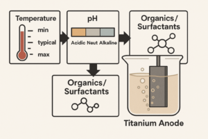
B) Temperature & pH & Organics/Surfactants
Temperature range (min/typical/max): higher T accelerates dissolution; we respond with denser microstructures, extra passes, or higher g/m².
pH window (acid/neutral/alkaline): acidic OER pushes toward Ir/Ta; neutral/alkaline can tolerate more Ru in CER-type duty.
Organics/surfactants: risk of fouling; we may specify smoother top layers, cleaning protocols, or anti-fouling touch-up passes.
Why it matters: These parameters tune phase stability and service-loss rate, thus impacting loading, pass count, and oxidation dwell.
C) Target Reaction / Duty
Chlorine evolution (CER) vs Oxygen evolution (OER) vs Cathodic protection vs Auxiliary anode for electroplating.
Each duty has a different overpotential window and stability requirement; we choose oxide family & ratio accordingly and adjust edge weighting and fixture strategy.
Why it matters: Reaction pathway sets the electrocatalyst family and voltage target, thus the formulation.
D) Current Density Profile & Allowable Voltage Drop
Mode: continuous or pulsed;
Current Density (J): your typical operating value (A/m² or A/dm²)
Voltage budget: maximum acceptable cell voltage or ΔV allowance.
Why it matters: Peaks and ΔV constraints drive thickness uniformity, per-pass wet-film limits, number of passes, and sometimes busbar/lead design to control ohmic loss.
E) Expected Lifetime & Warranty Conditions
Define lifetime at your J & electrolyte (e.g., years at J_avg, or Ah·m⁻² target).
If you require a warranty, specify the exact test basis (electrolyte, J, T, duty).
Why it matters: Lifetime targets determine precious metal loading (g/m²) & tolerance, pass count, and QC intensity—key cost drivers.
What to include in your RFQ (fast checklist)
Electrolyte (name, concentration) and halides present (Cl⁻/F⁻/Br⁻).
Temperature (min/typical/max), pH range, organics/surfactants (if any).
Target reaction/duty (CER/OER/CP/auxiliary plating).
Current profile (continuous/pulsed; J_avg, J_peak, duty cycle; allowable ΔV).
Lifetime goal / warranty basis (conditions + hours/years or Ah·m⁻²).
Geometry note (plate/mesh/tube/wire) for later 2.2 detailing of edges/holes weighting.
Information buyers provide to confirm process & pricing
Goal: With the least amount of info from you, we can lock the process, assess quality, and break down pricing. Below are 5 themes with buyer prompts → our standard replies/deliverables.
1) Coating & Drying
You can ask/provide:
Which method do you use—brushing / electrostatic spraying / roll coating? Do you have dedicated paths and fixtures to ensure coverage on edges/holes/bends?
What is the per-pass wet-film limit? How many passes do you typically apply per part?
What are the inter-pass drying criteria (temperature / time / mass constancy)?
Can you share your edge/hole/bend weighting strategy (thickened zones or targeted touch-up coats)?
Our standard reply/deliverables:
Route: Default brush coating; electrostatic spray for complex geometry; roll coat for flat parts & takt production.
Coverage strategy: We provide fixture and path diagrams (edge back-brushing, fan-shaped path at holes, directional touch-ups on bends).
Per-pass wet-film limit: Defined by recipe and written into SOP/COA (shipped with “≤ X µm”).
Pass count: Multi-pass per target loading (g/m²) and performance (e.g., Standard / Enhanced / High-load tiers).Drying criteria: 100–200 °C far-IR primary, hot-air assist if needed; release on stable mass/appearance, no tack, no solvent odor. Criteria appear in the routing card and batch records.
Edge/hole/bend weighting: Optional thickened zones or second touch-up passes per drawing, referenced in the drawing notes & COA.
2) Sintering & Inter-pass Cooling
You can ask/provide:
Can you include heating–soak–cooling curves with the shipment? Where are thermocouples (TCs) placed?
What charging method (vertical / horizontal / suspended), part spacing, and orientation ensure uniform temperature?
Do you force-cool to room temperature between passes? Are inter-pass cooling logs available?
Our standard reply/deliverables:
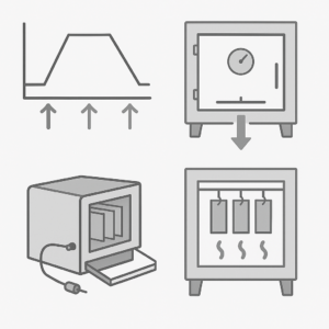
Temperature profiles: We can provide representative furnace cycle curves showing heat-up, dwell, and cooldown; with typical dwell ≥ 400 °C, 10–15 min per pass.
TC placement: Door-zone compensation, mid-chamber reference, and load-reference points (with placement schematic).
Furnace loading rules: Rationale for vertical/horizontal/suspended, minimum spacing, and orientation to avoid shadowed zones.
Inter-pass cooling: Forced cooling to room temperature after every pass; cooling start/end temp & time are recorded in batch records and can be shipped per lot.
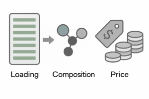
3) Loading & Composition (direct lifetime & price drivers)
You can ask/provide:
Target noble-metal loading (g/m²) and tolerance (e.g., ±10% or tighter)?
Coating composition (e.g., Ru:Ir, Ir:Ta, Pt) and system targeting (chlorine evolution / oxygen evolution)? Any alternative recipes to balance lifetime vs cost?
Rework/repair (strip-and-recoat) criteria & process? How are costs calculated?
Our standard reply/deliverables:
Loading & tolerance: We propose g/m² tiers aligned to your lifetime goal, with tolerance (standard ±10% or per your spec). The COA shows target / actual / uniformity stats.
Composition & targeting: Based on current density/frequency/electrolyte, we recommend Ru-rich (CER), Ir-Ta (OER), Pt (special use), etc., plus a Standard vs Economy vs Long-life comparison.
Rework/repair: Triggers (e.g., wipe shedding, resistance out-of-spec). Process: clean → strip → surface re-prep → thin multi-pass recoat → re-oxidize.
Costing: by area, target loading, furnace cycles, and inspections; we issue a repair quote sheet in advance.
4) Quality Control & Inspection
You can ask/provide:
What does factory inspection include? We recommend at least:
Appearance / pinholes (microscopic spot checks or spark-test threshold);
Loading (gravimetric and/or chemical strip, with uniformity statistics);
Adhesion / bend (methods & criteria, e.g., 180° bend with no visible flaking);
Electrochemical (polarization curves or accelerated-life conditions and hours).
Can you provide traceable batch records per lot: per-pass drying/sintering time & temperature, furnace ID, operator, cooling logs?
Our standard reply/deliverables:
COA: Includes appearance & pinhole sampling, loading target/actual, uniformity stats, adhesion/bend results, and key electrochemical data (per mutually agreed polarization/accelerated conditions).
Batch records: Pass-by-pass key parameters (drying/oxidation temps & times, TC locations, cooling records), furnace ID, operator signatures—available per lot.
Sampling plan: AQL/sample size & release criteria scaled to order size; critical lots ship with companion coupons and results.
5) Lead Time & Cost
You can ask/provide:
Standard takt (estimated time per pass) and max furnace area/lot size? Small-lot surcharge?
Are fixtures/molds a one-time charge? Can they be re-used after recipe or geometry changes?
Precious-metal price lock: by PO date, payment date, or shipment date? How are delays adjusted?
Our standard reply/deliverables:
Capacity & takt: Typical per-pass time, max loadable area/qty, and scheduling rules. Small/urgent lots that require line changeover / furnace clearing / dedicated fixturing may incur special charges.
Fixtures/molds: One-time charge based on complexity; after recipe/shape changes we assess reuse/modification and quote retrofit cost.
Price lock: Default PI confirmation + validity window; can lock on payment or shipment by agreement. If overrun for reasons beyond our control, the precious-metal portion adjusts by a market formula (pre-agreed in the PI).
Why can quotes differ even when you give the same operating conditions and g/m² loading?
Even if two suppliers receive the same stated conditions and the same noble-metal loading (g/m²), quotes can still vary a lot. Here are the main reasons—and how we handle them so you can compare fairly.
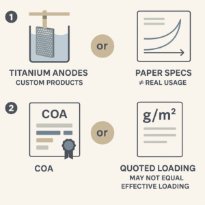
Reason 1 — Titanium anodes are custom products; “paper specs” ≠ real usage
Why it happens: Real cells differ from the datasheet: hydrodynamics, cleaning cycles, start/stop behavior, organics, local hotspots, busbar design, etc. These drive the actual coating choice, pass count, and sintering profile needed for lifetime.
Our approach: We recommend a small trial sample first. Your trial results (voltage trend, fouling, resistance drift, color change) let us tune the coating family, loading tier, edge weighting, and cooling cadence—so the final spec matches your line instead of a generic recipe.
Reason 2 — “Quoted loading” may not equal effective loading
Why it happens: Reported g/m² can be measured differently (gravimetric vs chemical strip), rounded, or quoted as a nominal range. In some markets it’s common to state higher g/m² than is effectively delivered, to make cross-quotes look expensive and discourage switching suppliers.
Our approach:
COA lists target vs actual loading and uniformity statistics, with the test method (gravimetric and/or chemical strip).
We’re happy to support third-party verification or provide companion coupons from the same furnace load.
If you share your lifetime target, we will price to the required performance rather than just a number on paper.
Reason 3 — You can’t lock both “exact g/m²” and “lifetime warranty” at once
Why it happens: Lifetime depends on more than grams: oxide family & ratio (Ru/Ir/Ta/Pt), layer architecture, per-pass thickness, sintering window, edge/holes weighting, and QC rigor. Two anodes with the same g/m² can have very different service lives—and different costs.
Choose one of these contracting models for apples-to-apples quotes:
Model A — Loading-specified contract
You fix the g/m² and tolerance (e.g., ±10%).
We guarantee: loading within tolerance and workmanship to spec.
Price basis: precious-metal content + processing.
Note: lifetime is indicative only (no performance warranty unless separately agreed).
Model B — Lifetime-specified contract (recommended for production)
You define operating conditions
Current density, J: ____ (A/dm² or A/m², typical; add J_peak if any)
Voltage / allowed rise: V_max = __ V or ΔV ≤ __ mV
Solution pH: ____ (value or range, e.g., 1–2 / 6.5–8.5)
Operating temperature: ____ °C (min / typical / max, e.g., 15 / 25 / 45)
Frequency: ① Continuous DC; or ② Pulsed: __ Hz, duty __ %
and lifetime/warranty.
We decide: coating system & exact loading to meet the target, and take performance responsibility.
Price basis: Precious Metal System and Precious Metal Content + extra process controls + risk/warranty coverage.
Outcome: the spec is optimized for your cell, not just a gram number.
What you can do to compare quotes fairly (quick checklist)
Tell us current density (J) and frequency (DC / Hz). If that’s all you have, we’ll default the rest on the safe side.
Decide which model you want (Loading-specified or Lifetime-specified).
Ask for COA with method (how loading is measured) and batch records scope (per-pass temps/times, furnace ID, cooling logs).
If feasible, run a trial sample—it’s the fastest way to converge to the right recipe and avoid paying for grams that don’t translate to lifetime.
Chapter 3:Support and Optimization
After sintering: how can a buyer quickly judge coating quality?
Keep it simple: do a quick wipe test, look at the color, and ask for basic furnace records. Here’s a plain-English guide you can use at incoming inspection.
1) Filter-paper wipe test (fast check of adhesion)
Goal: See if the coating is firmly bonded.
How: Use clean white filter paper (or lint-free white paper). Press and wipe the same spot 3–5 times in one direction.
Pass: The paper stays clean (no obvious black mark).
Fail / risk: Clear black marks on the paper → poor adhesion. Common causes:
Oxidation temperature too low.
A single pass was too thick (solvent trapped).
Next coat was applied before the part cooled fully to room temperature.
What to ask the supplier for this lot:
Per-pass drying/oxidation temperature & time.
Inter-pass cooling records (cooled to room temp each time).
2) Color check (over-temperature signal)
What to look for: A uniform bluish tint or blue patches often means over-temperature or over-soak during oxidation.
Why it matters: Can lead to bigger oxide grains → higher resistance, weaker adhesion, shorter life.
What to ask:
The zoned temperature settings and door-zone compensation used.
A sample furnace curve (heating → soak → cooling) for a representative load.
3) Proof of temperature uniformity (the “evidence pack”)
Why: When the door opens for loading/unloading, the door area cools down. Without zoned control (slightly higher setpoint near the door), the chamber becomes uneven, hurting coating quality.
Supplier documents you should request:
Zoned setpoints including door-zone compensation (so the whole chamber settles at the target temperature).
Thermocouple (TC) map: where TCs are placed (door zone, mid-chamber, load reference).
A representative furnace cycle showing: ramp, soak ≥ 400 °C for 10–15 min per pass, and cooldown.
Inter-pass cooling logs: start/end temperatures and time to room temperature for each pass.
How to judge: If these records are complete and match what you see (clean wipe test, normal color), temperature control is likely OK. If records are missing or don’t align with the part’s appearance, increase sampling or ask for re-test.
Quick acceptance checklist
Do the wipe test first: no black mark → likely OK; black mark → request temp/cooling records and re-check.
Scan the color: any overall/patchy blue → verify zone compensation and soak window.
Ask for the evidence pack: zoned setpoints, TC map, furnace curve, inter-pass cooling logs. Only release the lot when documents and visual checks agree.
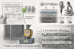
Is coating thickness tied to noble-metal loading and price?
Short answer: partly related, not one-to-one. A thicker MMO layer doesn’t automatically mean more grams of precious metals—or a higher price. Here’s why, and how to judge it correctly.
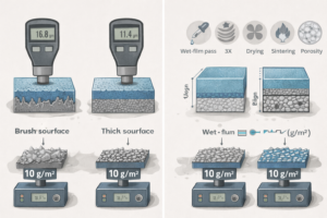
1) Brush coating needs a rougher surface → big thickness tolerance
Brush coating usually uses a roughened Ti surface to anchor the film. Roughness (Ra/Rz) makes the apparent thickness larger and more scattered, even if grams per square meter (g/m²) are the same.
Profilometers “ride the peaks and valleys,” so two parts with identical loading can show different thickness readings just from surface texture.
Takeaway: Thickness variation with brush coating is normal and not a direct proxy for precious-metal content.
2) Process variables vs. grams (g/m²)
Wet-film per pass, number of passes, drying completeness, sintering shrinkage, and layer porosity all change the final thickness—without changing grams in a linear way.
You can have a thin, dense microstructure with higher loading, or a thicker, porous layer with lower loading, depending on recipe and firing.
Takeaway: g/m² (mass) drives performance and cost; thickness is strongly affected by microstructure and sintering, not just mass.
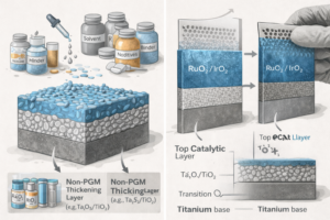
3) Additives, binders, and non-PGM oxides
MMO recipes include solids other than precious metals (e.g., Ta₂O₅/TiO₂ matrices), plus solvents, binders, and additives that tune flow, leveling, and pore formation.
These non-PGM solids and vehicles can increase thickness but don’t add grams of Ru/Ir/Pt in the same proportion.
Takeaway: More thickness can come from non-precious components or higher porosity, not from more PGM.
4) Transition/intermediate layers change thickness without equal grams
Brush-coated anodes may include transition layers (e.g., TiOₓ or Ta/Nb barrier layers) to improve adhesion and lifetime.
These add thickness but contain little or no precious metals compared with the top catalytic layers.
Takeaway: Layer architecture matters: thicker ≠ more PGM if much of it is barrier/transition material.
So… how should buyers use thickness to judge loading (sensibly)?
Use thickness as a screening check only—verify grams with a mass-based method.
Good practice
Ask for COA with loading (g/m²) and the test method (gravimetric and/or chemical strip).
Request companion coupons from the same furnace lot for independent verification.
If you still want a thickness check, ask the supplier for a recipe-specific calibration between thickness and g/m² (valid only for a defined roughness class, pass count, and sintering window).
Prefer cross-section microscopy (SEM/EDS) or stylus/optical profilometry on a reference flat. Be cautious: common paint/eddy-current gauges can be unreliable on conductive MMO oxides over titanium.
For mesh parts, geometric vs. real surface area differs—thickness is not a reliable indicator. Use g/m² on a known-area coupon processed with the lot.
Rule-of-thumb formula (use only with fixed, documented parameters)
Approximate loading L depends on thickness t × effective density ρ × (1 − porosity P) × PGM fraction in solids fPGM:
L ≈ t × ρ × (1 − P) × fPGM
However, ρ, P, and fPGM vary with the recipe and firing; the relation is valid only when those values are fixed and documented.
Pricing implications (why “thicker” doesn’t always cost more)
Price scales mainly with PGM grams and process complexity (passes, controls, QC)—not with visual thickness.
A well-designed dense microstructure can hit your lifetime target at lower g/m² (may look thinner, cost less, still perform).
Conversely, an under-fired or additive-heavy layer may look thick but underperform and doesn’t justify higher price.
Buyer checklist (quick)
Compare COA g/m² + method, not thickness alone.
If using thickness, demand a calibrated thickness→g/m² curve tied to roughness class & recipe.
For critical orders, request companion coupons, cross-section photos, and batch records (per-pass temps/times, cooling logs).
Decide pricing by required lifetime and verified g/m², not by the “look” of thickness.
Brush-coated MMO Titanium Anodes: common quality instabilities (coating & sintering) and quick fixes
Use this buyer-friendly guide at incoming inspection or supplier audits. Each topic shows what to ask, typical risks, how to prevent/fix, and what evidence to request.
Quick overview (one-page matrix)
Topic | Typical risks if uncontrolled | What good looks like | Evidence to request |
---|---|---|---|
Per-pass wet film (limit & target) | Trapped solvent → peeling/bubbles; high resistance; lot variability | Clear wet-film limit per recipe; comb gauge check online; gravimetric delta-mass per pass | Per-part weight distribution with g/m² conversion (L = Δm/A); per-pass weighing logs; comb-gauge records |
Operator & fixtures consistency | Edge/holes thickness scatter; runs | Trained operators, cross-checks, repeatable fixtures & paths | Training/qualification records; first-article comparisons; cross-shift consistency data; fixture drawings |
Defects (runs, pinholes, fisheyes, bubbles, orange-peel) | Early failure points; high leakage | Viscosity window, clean air, edge back-brushing, full drying 100–200 °C | Defect atlas, rework SOP + window (e.g., strip-and-recoat within last 2–3 passes), re-inspection results |
Atmosphere & O₂ control | Under-oxidation (unstable phase) or over-burn (grain growth) | Defined air/O₂ setting; verified flow/refresh; calibrated sensors | Gas setpoints & calibration logs; periodic checks; exception curves |
Furnace loading & uniformity | Door-zone cool-down, shadowing, local overheat | Proper vertical/horizontal/suspended loading, min spacing, door-zone compensation | Loading photos/diagram; multi-point temp comparison; heat–soak–cool curves (≥ 400 °C, 10–15 min/pass) |
System segregation (Ru-Ir / Ir-Ta / Pt) | Cross-contamination → life scatter | Separated furnaces/batches or strict clean-down | Chamber clean SOP, isolation batch records, fixture segregation list |
Sintering window & inter-pass cooling | Under/over-temp; poor interlayer bond | Soak ≥ 400 °C, 10–15 min/pass; forced cool to room temp every pass | Per-pass temp/time logs, cooling start/end temps, TC map, representative furnace cycle |
A) Per-pass wet film: limits, targets, and measurement
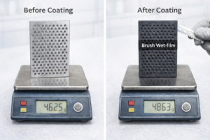
Ask: What is your per-pass wet-film limit/target? How do you measure it (comb gauge / weighing)?
Risks: No limit or too thick → incomplete drying, peel/bubble, high resistance.
Prevent: Define wet-film limit per recipe; control viscosity, brush load, overlap 30–50%; comb-gauge online, Δmass per pass offline.
Fix (this lot): Local light sand → thin touch-up → re-fire; if peel/black-wipe appears, follow strip-and-recoat SOP.
Evidence: Weight distribution per part + g/m² conversion (L = Δm/A) and per-pass weight logs (with photos of comb-gauge checks).
B) Operator qualification & fixture repeatability
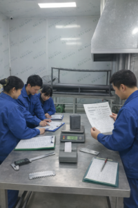
Ask: How do you ensure operator consistency, cross-checks, and fixture location accuracy?
Risks: Human variation → edge/hole scatter or runs.
Prevent: Training & test-out, first-article side-by-side, visual path arrows/takt on fixtures.
Fix: Local light sand + directional touch-up; if lot scatter is high, add one uniform thin pass then re-fire.
Evidence: Training files, first-article reports, cross-shift data, fixture drawings.
C) Defects: runs / pinholes / fisheyes / bubbles / orange-peel
Ask: How do you prevent these? What is the rework standard if they appear?
Risks: Leak paths, early failure.
Prevent: Hold viscosity & wet-film limits, clean airflow, edge back-brush & fan path at holes, complete drying at 100–200 °C.
Fix:
Minor: local light sand → thin recoat → re-fire.
Multiple areas: overall light sand → uniform thin pass → re-fire.
Black-wipe/bubbles: strip-and-recoat within the defined rework window (e.g., within last 2–3 passes).
Evidence: Defect atlas, rework SOP + window, post-rework inspection.
D) Atmosphere & oxygen control
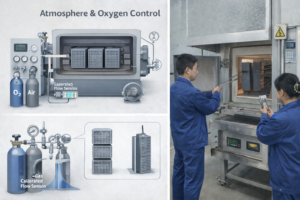
Ask: Air or oxygen-enriched? How do you verify refresh rate/flow and O₂ partial pressure?
Risks: Low O₂ → under-oxidation; too high + over-soak → grain growth, de-chlorination, higher resistance.
Prevent: Fixed gas setpoints, measured flow/refresh, calibrated sensors.
Fix: If under-oxidized, extend/redo soak; if over-burn (bluish tint, high R), dial back next lot, optionally redo last 1–2 passes.
Evidence: Gas setpoints, calibration logs, periodic check sheets, exception curves.
E) Furnace loading: orientation, spacing, and door-zone compensation
Ask: Vertical/horizontal/suspended? What spacing/orientation avoids shadowing?
Risks: Door-zone cool-down, stacked parts, hot spots → non-uniform temperature.
Prevent: Choose loading mode by geometry; keep minimum spacing; apply door-zone temperature compensation; multi-point thermocouples.
Fix: For suspect lots, re-fire reference coupons or add a uniform thin pass and re-fire.
Evidence: Loading diagram/photos; multi-point temperature comparison; zone setpoints & door compensation; furnace curves (≥ 400 °C, 10–15 min/pass).
F) System segregation & cross-contamination
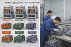
Ask: Are Ru-Ir / Ir-Ta / Pt run in separate furnaces/batches? What’s the anti-cross-contamination plan?
Risks: Mixed residues → surface contamination, phase shift, lifetime scatter.
Prevent: Separate or strict clean-down; fixture segregation.
Fix: If contamination is found: strip-and-recoat; audit clean-down.
Evidence: Chamber clean SOP, isolation batch records, fixture logs, trace-back reports.
G) Sintering window & inter-pass cooling (critical checks)
Ask: Do you force-cool to room temp between passes? Is the temperature window fully achieved?
Risks: Warm recoating → weak interlayer bond; over/under-temp → resistance up / unstable phase.
Prevent: Soak ≥ 400 °C, 10–15 min per pass; forced cool to room temp every pass.
Fix: Under-temp → complete soak or add uniform thin pass; over-temp (bluish/high R) → retune zones & door compensation, possibly redo last 1–2 passes.
Evidence: Per-pass temp/time logs, cooling start/end temps & durations, TC map, representative furnace cycle.
Defect cheatsheet (symptom → likely cause → quick fix → prevent next lot)
Symptom | Likely cause | Quick fix (this lot) | Prevent next lot |
---|---|---|---|
Black wipe mark | Under-temp; too-thick pass; recoated warm | Strip-and-recoat; or light sand + thin pass + re-fire if minor | Enforce wet-film limit; full dry; force-cool to room temp |
Bluish tint | Over-temp / over-soak; door-zone over-comp | Redo last 1–2 passes at correct window | Map furnace; tune zoned control & door compensation |
Runs / sags | Low viscosity; too thick; vertical pooling | Local sand → thin touch-up → re-fire | Hold viscosity; edge back-brush; fan path at holes |
Pinholes / fisheyes | Dust/oil; incomplete drying | Local recoat or strip/recoat within window | Clean air; 100–200 °C full drying; fixture hygiene |
High resistance scatter | Non-uniform thickness; over-burn; under-dry | Add uniform thin pass + correct soak | Per-pass weighing; soak window control; inter-pass cooling |
Buyer action list (fast)
At receiving: filter-paper wipe, low-angle light check, color scan.
Ask for the evidence pack: zoned setpoints + door compensation, TC map, furnace curve, inter-pass cooling logs.
Quantify: per-part weight distribution + g/m², per-pass weighing logs, comb-gauge checks.
For defects, follow the rework window; beyond window → scrap to protect schedule.
For different systems, require separate furnaces or clean-down records to avoid cross-contamination.
Chapter 4:Summarize
How Ehisen Helps You Get Repeatable Quality?
At Ehisen, we know that great titanium anodes don’t come from formulas alone—they come from stable coating and sintering. Our role is more than supplying parts. We work as your process partner so the coating you buy delivers the life, consistency, and cost you expect.
We start from your operating window and lock down the key steps together: the coating system and ratio, the per-pass wet-film limit and pass count, complete drying at 100–200 °C, and a clear oxidation profile (at least 400 °C, 10–15 min per pass). We apply zoned temperature control with door-area compensation, force-cool to room temperature between passes, and provide edge/hole weighting paths and practical fixtures for uniform coverage.
To make quality visible and auditable, every lot can ship with a thermocouple (TC) map, furnace heat–soak–cool curves, per-pass time/temperature logs, inter-pass cooling records, and a COA. If you need to tune lifetime vs. cost, we run trial samples and small DOEs. For common issues (runs, pinholes, bluish over-burn), we share rework windows and SOPs, and offer remote or on-site training so your team can execute the process the same way every time.
From first samples to ramp-up and after-sales (including recoat/refurbish), we back you with clear lead times, a precious-metal price-lock plan, and continuous improvement. Let’s build a coating & sintering process that is stable, repeatable, and fully traceable—so every batch turns into reliable output and long-term value.
Supply & services
Our value go beyond titanium processing
Finding a reliable processor of titanium products is essential to your business success, and Ehisen is here to be that partner.